
Manual


CF 66 54 Rev. C 2/05
• “ON” means that the display will update four times each second. The channel’s values will be averaged for ¼
second, then displayed.
• “OFF” means that the channel’s display will update as quickly as possible.
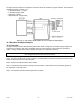
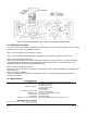
12.6.3 AUXn FUNCTION Menu Items
The AUX1 FUNCTION and AUX2 FUNCTION menu items determine what happens when the Auxiliary Function
pins (labeled as “AUX1” and “AUX2”) on the channel’s connector are activated. These pins are “activated” when
connected to the (-)Signature (labeled as “-MEM”) pin. The choices are:
• “DISABLED” means that activating the pin does nothing.
• “TRACK HOLD” means that the tracking, peak and valley values will not be updated.
• “HIGH/LOW HOLD” means that the peak and valley values will not be updated.
• “HIGH/LOW CLEAR” means that the peak and valley values are reset.
• “TARE ON” activates the channel’s Tare function (resets it to zero).
• “TARE OFF” deactivates the channel’s Tare function.
As the Auxiliary Function pins are not isolated, it is recommended that a push-button switch or relay is used to
connect these pins to the Digital Ground pin.
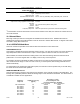
12.6.4 CALIBRATION TYPE Menu Item
This chooses the type of calibration technique to be used. There are two methods that can be used to calibrate the
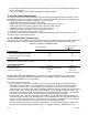
transducer to the Input Channel. Each has advantages and disadvantages as described in the table below.
Table 12-1: Comparison of Calibration Types
Shunt Calibration
2-, 3- or 5-point Known
Load
Calibration
RECOMMENDED…
…for most applications No Yes
…when frequently swapping transducers Yes No
…when best possible accuracy required No Yes
PROS and CONS
Relative accuracy Good Best
Requires actual, calibrated loads to be applied No Yes
CALIBRATION TECHNIQUE
Zero-scale point from… Applied load Applied load
Full-scale point from… Transducer output when Shunt Cal pins
connected
Applied load
Linearity correction from…
N/A
2-point: none
3- or 5-point: applied load
It is important to know your application in order to select the appropriate calibration type. When the best
possible accuracy is required, Known-Load Calibration is recommended. However, if known loads are not
available, Shunt Calibration may be used instead.
The choices for this menu item are:
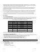
• “TYPE=SHUNT CAL” means Shunt Calibration. First, you are prompted to apply the load entered in the
“ZERO SCALE VALUE” register. Next, the instrument interconnects the Shunt Cal 1 and Shunt Cal 2 pins.
This activates the transducer’s or in-line amplifier’s shunt calibration circuit, which causes a predictable
apparent signal. The instrument then takes a reading and adjust itself using the “SHUNT CAL VALUE” register.
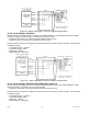
• “TYPE=2 POINT CAL” means 2-Point Known Load Calibration. You are prompted to apply the loads to the
transducer that were entered in the “KNOWN POINT 1/2” and “KNOWN POINT 2/2” registers. This technique
assumes that the transducer is linear, so the usual loads used are zero scale and full scale
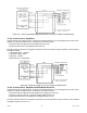
• “TYPE=3 POINT CAL” means 3-Point Known Load Calibration. You are prompted to apply the loads to the
transducer that were entered in the “KNOWN POINT 1/3” and “KNOWN POINT 2/3” and “KNOWN POINT 3/3”
registers. This technique can be used to compensate for the non-linearity in the transducer. The usual loads
used are zero scale, half scale, and full scale, but you are not restricted to these loads.
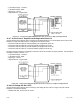
• “TYPE=5 POINT CAL” means 5-Point Known Load Calibration. You are prompted to apply the loads to the
transducer that were entered in the “KNOWN POINT 1/5”, “KNOWN POINT 2/5”, “KNOWN POINT 3/5”,