
Manual
CF 66 60 Rev. C 2/05
Analog Output Incorrect
Make certain of the type of Analog Output to a known output. Then, adjust your readout device, panel meter, PLC
or data acquisition system to match.
Check the output selection jumpers; see “Output Selection”.
“APPLY 00000” on Power-up
the channel has detected that the transducer connected to the instrument is different than the one the channel was
last calibrated with. Because the CALIBRATION TYPE is set to Shunt Calibration, the instrument is prompting you
to apply zero load in order to calibrate to this new transducer.
Do one of the following, depending on the situation:
• Re-connect the original transducer to the channel and re-start the instrument.
• Press [ENTER] to re-calibrate the channel to this new transducer using Shunt and accept the presently applied
load as “0”. (In situations where on can’t apply “0” load to an absolute pressure transducer or a load cell with a
preload, you can change the CALIBRATION DATA->ZERO-SCALE VALUE menu item from “0” to a load that
can be applied. For example, 14.7 PSIA or the known preload on the load cell.
• Use the CALIBRATE menu item to perform a Known-Load Calibration with this new transducer.
Auxiliary Function Pins Not Operating
Make sure that the AUX1 FUNCTION or AUX2 FUNCTION SETUP menu items are set correctly; if they are set to
DISABLED then they will not operate.
The Auxiliary Function (“AUX1” and “AUX2”) pins must be connected to pin 10, not pin 8, to activate them.
Sensitivity to EMI/RFI
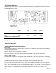
To obtain maximum immunity to electromagnetic or radio frequency interference, make certain that the shields of
the transducer cables are connected to the “cable shield connection screw” on the rear panel of the instrument.
See “Wiring”, “External Arrangement of AC powered DFI 1550 and DFI 1650” and “External Arrangement of DFI
SC3004”.
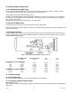
13.0 RELAY OUTPUT CHANNEL
13.1 Features
13.1.1 First Channel Installed
The first Relay Output channel installed in an instrument supplements the standard four limits (Limit 1, Limit 2, Limit
3 and Limit 4). Its four, dry contact relay outputs will mirror the Limit Outputs pins of the System connector.
In the SYSTEM->CONFIGURATION sub-menu, channels of this type are identified as LIMIT 01-04.
13.1.2 Second Channel Installed
The second Relay Output channel installed in an instrument adds another four limits to the instrument (Limit 5, Limit
6, Limit 7 and Limit 8). Its relay outputs show the status of these limits.
In the SYSTEM->CONFIGURATION sub-menu, channels of this type are identified as LIMIT 05-08.
13.1.3 Third Channel Installed
The third Relay Output channel installed in an instrument adds another four limits to the instrument (Limit 9, Limit
10, Limit 11 and Limit 12). Its relay outputs show the status of these limits.
In the SYSTEM->CONFIGURATION sub-menu, channels of this type are identified as LIMIT 09-12.
13.1.4 Fourth Channel Installed
The fourth Relay Output channel installed in an instrument adds another four limits to the instrument (Limit 13, Limit
14, Limit 15 and Limit 16). Its relay outputs show the status of these limits.