
Manual

CF 66 62 Rev. C 2/05
• “OFF” will turn the relay off.
RELAY 3 Menu Item
The options for this menu item are:
• “ON” will turn the relay on.
• “OFF” will turn the relay off.
RELAY 4 Menu Item
The options for this menu item are:
• “ON” will turn the relay on.
• “OFF” will turn the relay off.
14.0 DAC OUTPUT CHANNEL
14.1 Features
The DAC Output channel uses a digital-to-analog converter to generate a voltage or current from any channel’s
track, peak or valley value. This type of channel is often used to provide a Mathematics Virtual channel with an
analog output.
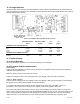
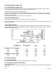
14.2 Wiring
Connect your readout instrument to a DAC Output channel by wiring it to the 12-pin connector of that channel. The
System Calibration Sheet that shipped with the instrument describes which cards are installed in each channel.
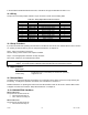
The pin-out for this connector is shown on the following table.
Table 14-1: DAC Output Channel Pin Connections
Pin Label Function Reference Pin
1 (top) N/C No connection
2 N/C No connection
3 N/C No connection
4 N/C No connection
5 N/C No connection
6 N/C No connection
7 +OUT Analog Output 8
8 -OUT Analog Return -
9 N/C No connection
10 N/C No connection
11 N/C No connection
12 (bottom) N/C No connection
The Analog Output and Analog Return pins are electrically isolated from all other pins on the instrument.
14.3 Setup Procedure
If you are not familiar with operating the instrument in SETUP menu mode, see “SETUP Menu mode”. A listing of
all menu items is given in “Setup Menu Reference” in Chapter 18.
Step 1: Determine if you have a Voltage DAC Output channel or a Current DAC Output channel check the
instrument’s System Calibration Sheet, or see “Identifying the Output Type” in Section 14.6.
Step 2: Wire the readout instrument to the channel’s connector. See the “Wiring” section earlier in this chapter for
details.
Step 3: Select the value (channel and source) used to drive the Analog Output. See the “Channel Menu” for
details.
Step 4: Select the full-scale and zero-scale settings used to drive the Analog Output. See the “Channel Menu” for
details.