
User Manual

CF11 6 V-May 2003-008-0186-00
4.3 Scaling Adjustment
Scaling adjustment permits the DFI 7000 to display values in the engineering units desired by the customer.
Adjustment can be made either with shunt calibration or with a known pressure or load on the transducer. Perform
the scaling adjustment right after the span is adjusted, using the same output voltage to assist in calibration of
scaling.
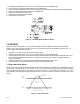
First, determine the desired full-scale value of a 15,000-pound unit load cell. The desired full-scale value would be
15,000 since a 41/2 digit indicator is capable of indicating a maximum of 19,999 counts. Calculate the expected
display value based on the voltage calculated in the span adjustment steps 4.2.1 or 4.2.2) as follows:
Shunt Cal Output in mv/v
x Full Scale Display = Shunt Cal Display
Full Scale Output in mv/v Value Value
EXAMPLE:
1.4883 mv/v x 15,000 lbs. = 11,819 lbs.
1.8888 mv/v
After this calculation is made, proceed as follows:
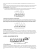
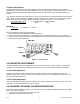
1. Depress the SHUNT CALIBRATION button (see figure3).
2. Adjust the SCALING potentiometer to yield the displayed value calculated above (11819 in the example).
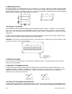
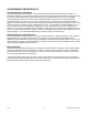
3. Place the jumper in the proper place on the Display Board to locate the decimal point as illustrated in Figure 2.
4. Reinstall the front panel and bezel.
Figure 2 – Decimal Points
5.0 OPERATIVE ADJUSTMENTS
Operative adjustments are those adjustments that may be made from time in normal operation. These include
“tweaking” the FINE ZERO and the FINE SPAN if these have moved, and setting the LIMITS potentiometers.
5.1 Fine Zero Adjustment
Transducers usually have some small amount of zero drift, usually the result of temperature change at the
transducer itself. With no pressure or load on the transducer, the zero may be readjusted to read zero by use of
the front panel ZERO adjustment
5.2 Fine Span Adjustment
After the FINE ZERO is readjusted, press the SHUNT CAL button to determine if the span is correct. If it needs
adjustment, use the SPAN adjustment on the front panel.
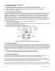
6.0 CHANGING THE SHUNT CALIBRATION RESISTOR
To change the Shunt Calibration Resistor, it is necessary to remove the Signal Conditioner Board from the Main
Board. The steps involved are:
1. Unplug the AC power and remove the rear connecter.
2. Remove the bezel and front panel (lens).