
User Manual

DFI INFINITY CS Quick Start Manual
Use this Quick Start Manual to set up your Strain Meter and
begin operation. Information is provided on how to:
• Connect ac power • Set basic options for operation
Connect the sensor • Scale the meter.
Features with are for the “B” version which has three-
color programmable “Big” LED display - All segment
characters shown are for the “B” version.
IMPORTANT: For complete information on all setup options,
please refer to the Operator’s Manual.
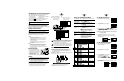
Mount the Unit
1. Cut a panel opening using the
dimensions shown to the right.
2. Position the unit in the opening,
making sure the front bezel is
flush with the panel.
3. Install retaining clips on both
sides of the meter and tighten against the panel.
Wiring
1. Remove the panel at the back of the unit.
2. Locate the TB1 connector.
3. Insert the correct wire in each terminal as shown in the
following figure and tighten the lockdown screws.
4. Tug gently on the wires to verify the connections.
Connect the Sensor
1. Locate the TB2 connector on the rear of the unit.
2. Attach the sensor wires and tighten the lockdown screws.
The diagram below shows the wiring for bridge sensors
with internal excitation.
NOTE: Refer to the Operator’s Manual for setup requirements
for other sensor types.
Bridge Sensor with Internal Excitation
3. Tug gently on the wires to verify the connections.
4. Replace the panel at the back of the unit.
Using the Configuration Menu
To configure the meter, you use the buttons on the front panel.
To: Take This Action:
Display the Press the MENU button. The first function
Configuration Menu on the menu, INPT, displays.
Select a submenu 1. Press MENU until the function you
function want is shown.
2. Press 䊳/TARE.
The information you can change flashes.
Select a value 1. Press 䊱/NT/GRS to display the option
for that submenu you want.
function 2. Press MENU to store it.
STRD quickly flashes, indicating that
the selection has been stored in memory.
Then the next menu function displays.
Go back to previous Press RESET once.
menu function
Exit the Press RESET twice. The unit displays
Configuration RST as it reinitializes. When a numeric
Menu value displays, the unit is in run mode.
(Optionally, you can press MENU to
move through all the menu functions
until the unit reinitializes.)
NOTE: This Quick Start Manual includes specific configuration
parameters for bridge sensors with an output range of 0–100 mV
and 10 V excitation. Other sensor types may require different
parameters or additional ones. When this is the case, we refer you to
the Operator's Manual for detailed instructions.
2
34
Warning: Do not connect AC power to your device until you
have completed all input and output connections. This
device must only be installed by a specially trained
electrician with corresponding qualifications. Failure to
follow all instructions and warnings may result in injury!
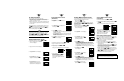
AC Powered Unit Connections
DC Powered Unit Connections
When using DC power, do not use internal excitation or
Isolated Analog Output for high color brightness. For low
or medium brightness, internal excitation is limited to
24 V @ 25 mA; 5 V, 10 V, 12 V @ 35 mA.
To Set the Input Type
1. Press MENU until the unit displays:
2. Press 䊳/TARE. The unit displays:
3. For this application you want 100M. If 100M is not
displayed, press 䊱/NT/GRS until it appears. Other choices
are 50M, 10V, 5V and 0-20.
NOTE: Refer to the Operator's Manual for more information
on changing ranges.
4. Press MENU to select the sensor shown. The meter
displays the next menu item. If you changed input type,
the meter displays:
To Set the Decimal Point
1. If it's not already shown, press MENU
until the unit displays:
2. Press 䊳/TARE. The unit displays:
3.
Press 䊱/NT/GRS to move the decimal
point to the desired location. The
factory settings is FFFF. The other
choices are F.FFF, FF.FF, and FFF.F.
4. Press MENU to select the decimal point position shown.
The unit displays:
MENU SUBMENU 䊳/TARE DESCRIPTION
INPT 100M,±50M,!10V , !±5V , 0-20
*
Input
DEC.P FFFF
*
, F.FFF, FF.FF, FFF.F Decimal Point
RD.S.O IN!1, RD!1, IN!2 , RD!2 Scale and Offset
RD.CF R.1=T
*
, R.1=N
Reading Configuration
R.2=0, R.2=1, R.2=2, R.2=3, R.2=4
*
R.3=F
*
, R.3=U
R.4=P, R.4=G
COLR GRN, RED, AMBR Display Color
S1.CF S.1=A
*
, S.1=B
Setpoint 1 Configuration
S.2=U
*
, S.2=L
S.3=N
*
, S.3=G
shown if R.4=G
S2.CF S.1=A
*
, S.1=B
Setpoint 2 Configuration
S.2=U
*
, S.2=L
S.3=N
*
, S.3=G
shown if R.4=G
S1.DB 0003
*
Setpoint 1, Deadband
S2.DB 0003
*
Setpoint 2, Deadband
OT.CF O.1=E
*
, 0.1=D Analog Output
O.2=C
*
, 0.2=V
Configuration
O.3=A
*
, 0.3=P
OT.S.O RD!1, OUT1, RD!2 , OUT2
Output Scale & Offset
LK.CF RS=E
*
, RS=D
Lockout Configuration
SP=E
*
, SP=D
L3=0
*
, L3=1
BRIT M.BrT, L.BrT, H.BrT
Display Brightness
Safety Consideration
This device is marked with the international Caution symbol.
The instrument is a panel mount device protected in
accordance with Class I of EN61010-1 (AC units) and Class III
(DC units). Remember that the unit has no power-on switch.
Building installation should include a switch or circuit-breaker
that must be compliant to IEC 947-1 and 947-3.
SAFETY:
• Do not exceed voltage rating on the label located on the
top of the instrument housing.
• Always disconnect power before changing signal and
power connections.
• Do not use this instrument on a work bench without its
case for safety reasons.
• Do not operate this instrument in flammable or explosive
atmospheres.
• Do not expose this instrument to rain or moisture.
EMC:
• Whenever EMC is an issue, always use shielded cables.
• Never run signal and power wires in the same conduit.
• Use signal wire connections with twisted-pair cables.
• Install Ferrite Bead(s) on signal wire close to the instrument if
EMC problems persist.
* Factory Default Settings
In order to maintain the same degree of protection as the
AC units, always use a Safety Agency Approval DC source
with the same Overvoltage Category and Pollution Degree.
External Fuse Required:
Time-delay, UL 248-14 listed Time-lag, IEC 127-3 recognized
175 mA (115 Vac line) 125 mA (115 Vac line)
80 mA (230 Vac line) 63 mA (230 Vac line)
10-32 Vdc, 7.5 W