
Instruction Manual
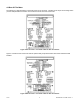
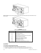
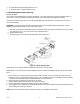


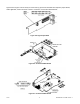
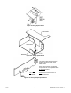
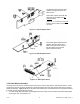
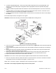


Figure 5-3. Transformer Jumpers
5.2.3 Printed Circuit Board(s) Installation
To install optional printed circuit board(s):
1. “Reveal the Main Board” (refer to Section 5.2, Disassembly).
2. Using Figure 5-4 as a reference, insert option board(s) into the corresponding slot(s) on the main board. Each
circuit board is keyed to fit in it’s own position.
Figure 5-4. Optional Printed Circuit Board Locations
5.2.4 How To Access Jumpers
To gain access to jumper S1 and S2 used to configure input type remove the mounting sleeve. The jumpers may
be accessed through the slot in the case.
To gain access to jumpers on the main board for power, excitation and lockout selection:
1. “Reveal the main board” (refer to Section 5.2, Disassembly).
NOTE: To access the S1 and S2 jumpers on the Signal Input Board, you only need to remove the mounting
sleeve.
2. To re-assemble the meter, follow the steps in reverse order.
CF 67 10 M1291/N/0403 11279ML-02 Rev. A