
Instruction Manual
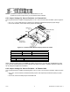
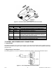

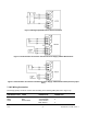
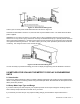


Figure 7-9. AC Connector Wiring at P1
Connect your AC meter power as described above and as shown in Figure 7-9.
CAUTION: As mentioned in Section 5.2.2, the meter has no power ON/OFF switch. The meter will be ON when
power is applied.
WARNING: Do not connect ac power to your meter until you have completed all input and output connections.
Failure to do so may result in injury! This device must only be installed electrically by a specially trained electrician
with corresponding qualifications. The main power input to the unit as well as the AC input signal to be measured
must agree with the wiring instruction. The meter is factory set to the power specified by the customer at the time
of ordering. The voltage is printed on the Product ID Label.
Figure 7-10. DC Connector Wiring at P1
You are now ready to proceed with scaling your meter to display in engineering units as described in Section 8.
8.0 METHODS FOR SCALING THE METER TO DISPLAY IN ENGINEERING
UNITS
8.1 Introduction
There are two basic methods for scaling your meter to display engineering units; scaling by using measured input
values or scaling without connecting a sensor using assumed input values. Both methods use the Input Scale and
Offset (“IN.SC.OF”) method.
8.2 Setup Meter Input Type and Range
If you have received your meter setup for your required input and do not require changes or rescaling, skip this
section entirely and proceed with the normal use of your meter.
If you received your meter and you only require a scaling change, proceed with the steps in Section 8.2.2.
CF 67 21 M1291/N/0403 11279ML-02 Rev. A