
Instruction Manual
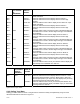
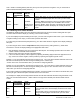

“L2C.8=0” FIL CNF (adaptive/fixed filtering and for which output(s)) can be chosen.
“L2C.8=1” FIL CNF (adaptive/fixed filtering and for which output(s)) cannot be chosen.
* The ‘MIN’ button allows you to sequence through L2C.1, L2C.2, L2C.3, L2C.4, L2C.5, L2C.6, L2C.7, and L2C.8.
The ‘MAX’ button allows you to select the “0” or “1” state for each “L2C” condition.
The ‘MENU’ button stores the selected values for all “L2C” condition(s) changed and advances the meter to “L3
CNF”. Do not press the ‘MENU’ button after each change within the submenu or the meter will advance to the next
menu item.
Every underlined “0” or “1” state is the factory preset value.
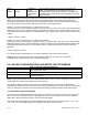
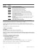
MENU
BUTTON
MAIN MENU
MIN/MAX*
BUTTON
SUB MENU
CONDITION
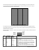
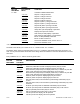
LOCKOUT CONFIGURATION #3
“L3C.1=0” FIL TI (# of samples in average) can be chosen.
“L3C.1=1” FIL TI (# of samples in average) cannot be locked out.
“L3C.2=0”
SP CNF (mode of action of setpoints 1 & 2 LEDs, transistors and relays) can be
selected.
“L3C.2=1” SP CNF (mode of action of setpoints 1 & 2 LEDs, transistors and relays) cannot
be locked out.
“L3C.3=0” AL CNF (mode of action of Setpoints 3 & 4, often used as alarms) can be locked
out.
“L3C.3=1” AL CNF (mode of action of setpoints 3 & 4, often used as alarms) cannot be
locked out.
“L3C.4=0”
AL FNC (Setpoints 3 & 4 independent or ganged with Setpoints 1 and 2) can be
selected.
“L3C.4=1” AL FNC (Setpoints 3 & 4 independent or ganged with Setpoints 1 and 2) cannot
be accessed.
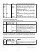
“L3C.5=0”
AL RDG (# of out-of-range readings before trip of setpoints 3 & 4) can be
selected.
“L3C.5=1” AL RDG (# of out-of-range readings before trip of setpoints 3 & 4) cannot be
accessed.
“L3C.6=0” SP DB (hysteresis or deadband of Setpoints and Alarms) can be specified.
“L3C.6=1” SP DB (hysteresis (deadband) of Setpoints and Alarms) cannot be accessed.
“L3C.7=0”
OUT.CNF (analog & BCD outputs, setpoint display flashing) can be specified.
“L3C.7=1” OUT.CNF (analog & BCD outputs, setpoint display flashing) cannot be
accessed.
“L3C.8=0”
OT.SC.OF (2-data-point method for independent analog-output scale/offset) can
be entered.
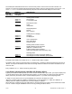
“L3 CNF”:
“L3C.8=1” OT.SC.OF (2-data-point method for independent analog-output scale/offset)
cannot be accessed.
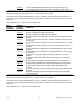
* The ‘MIN’ button allows you to sequence through L3C.1, L3C.2, L3C.3, L3C.4, L3C.5, L3C.6, L3C.7, and L3C.8.
The ‘MAX’ button allows you to select the “0” or “1” state for each “L3C” condition.
The ‘MENU’ button stores the selected values for all “L3C” condition(s) changed and advances the meter to “L4
CNF”. Do not press the ‘MENU’ button after each change within the submenu or the meter will advance to the next
menu item.
Every underlined “0” or “1” state is the factory preset value.
CF 67 33 M1291/N/0403 11279ML-02 Rev. A