
Instruction Manual


For “RDG OF”, you may choose to enter a reference temperature offset here (e.g., “-100.00”) so that the display will
read deviation of the input from the boiling point (or some other temperature).
If “RDG.1 = 1” were chosen, then you go automatically into “RD.SC.OF”.
NOTE: Direct reading offset “RDG OF” now has programmable decimal point position. This makes the decimal
point independent of the display decimal point and allows larger offset values.
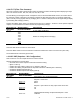
MENU BUTTON
MAIN MENU
MIN/MAX*
BUTTON SUB
MENU 1
MIN/MAX
/MENU** BUTTON
SUB MENU 2
DESCRIPTION
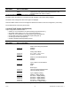
READING SCALE & OFFSET
INPUT 1
Item #1 of Coordinate #1.
000000. (“00000.0”)
Enter the first value displayed by the meter.
READ 1
Item #2 of Coordinate #1.
000000. (“00000.0”) Enter first desired value.
INPUT 2
Item #1 of Coordinate #2.
000000. (“10000.0”) Enter the second value displayed by the meter.
READ 2 Item #2 of Coordinate #2.
“RD.SC.OF”:
000000. (“10000.0”)
Enter second desired value.
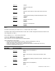
* The ‘MIN’ button allows you to sequence through “INPUT 1”, “READ 1”, “INPUT 2”, and “READ 2” headings.
The ‘MAX’ button sends you to the value corresponding to “INPUT 1”, “READ 1”, “INPUT 2”, or “READ 2” so you
can change it (go to the SUB MENU 2 item).
** The ‘MIN’ button allows you to step through the digits of the applicable number being changed.
The ‘MAX’ button changes the value of the digit to be displayed.
The ‘MENU’ button stores the selected values for each input required in “RD.SC.OF”. After the last value (“READ
2”) has been entered and the ‘MENU’ button is pressed, the meter display will advance to “IN CNF”.
Every underlined item is the factory preset value.
NOTE: Meter now stores all scale and offset values for “IN.SC.OF”, “RD.SC.OF”, and “OT.SC.OF”.
The meter will display previously input values when entering these menus. If system decimal point changes, all
values will be modified accordingly; if overflow occurs meter will flash that parameter with 9999999.
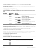
9.2.4 IN CNF (Input Configuration)
Input configuration is used to select:
• 50 or 60 Hz line frequency [INP.1]
• slow or fast read rate [INP.2]
• unipolar or bipolar inputs
• cold junction compensation [INP.5]
INP.1 and INP.2 are related to each other. If your power requirements require 50 Hz, you can have optimum
integration in FAST read mode (12/sec). In the FAST mode, you need a jumper in the
S1A position on the vertical Signal Input Board. If you set the SLOW read rate, this jumper should be removed to
avoid overloading the integrator. SLOW read rate produces less noise.
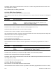
MENU BUTTON
MAIN MENU
MIN/MAX/MENU *
BUTTON SUB MENU
DESCRIPTION
INPUT CONFIGURATIONS
Line Frequency:
“IN CNF”:
“INP.1=0”
60 Hz
CF 67 36 M1291/N/0403 11279ML-02 Rev. A