
Instruction Manual


Alarm 2 open-collector or relay output Active ON or OFF:
“ALC.5=0”
On
“ALC.5=1” Off
Filtered/unfiltered reading compared with Alarm 2 (Setpoint 4) value:
“ALC.6=0” Unfiltered
“ALC.6=1” Filtered
Alarms 1 & 2 (Setpoints 3 & 4) action and LEDs:
“ALC.7=0” Enabled
“ALC.7=1” Disabled
Alarm reset at P2-11 connector:
“ALC.8=0”
Disabled
“ALC.8=1” Enabled
* The ‘MIN’ button allows you to sequence through ALC.1, ALC.2, ALC.3, ALC.4, ALC.5, ALC.6, ALC.7 and ALC.8.
The ‘MAX’ button allows you to select the “0” or “1” state for each “ALC” condition.
The ‘MENU’ button stores the selected values for each “ALC” condition changed and advances the meter to the
next configuration (“AL FNC”).
Every underlined “0” or “1” is the factory preset value.
9.2.12 AL FNC (Alarm Function)
Refer to Section 10 for an in-depth discussion of these features. Alarm function is used to select:
• whether the alarms are used in the process, high-deviation, low-deviation or band deviation modes [ALF.1 &
ALF.3]
• whether or not to latch the alarms [ALF.2 & ALF.4]
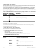
MENU BUTTON
MAIN MENU
MIN/MAX/MENU *
BUTTON SUB MENU
DESCRIPTION
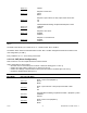
ALARMS 1 & 2 FUNCTION:
Alarm 1 State:
“ALF.1=0”
Process Mode
“ALF.1=1” High Deviation Mode
“ALF.1=2” Low Deviation Mode
“ALF.1=3” Band Deviation Mode
Alarm 1 Latch Action:
“ALF.2=0”
Unlatched
“ALF.2=1” Latched
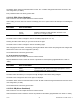
Alarm 2 State:
“ALF.3=0”
Process Mode. Process Mode means the deadband is equally
above and below the setpoint.
“ALF.3=1” High Deviation Mode
“ALF.3=2” Low Deviation Mode
“ALF.3=3” Band Deviation Mode
Alarm 2 Latch Action:
“ALF.4=0” Unlatched
“AL FNC”:
“ALF.4=1” Latched
* The ‘MIN’ button allows you to sequence through ALF.1, ALF.2, ALF.3 and ALF.4.
The ‘MAX’ button allows you to select the “0”, “1”, “2”, or “3” state for each “ALF” condition.
CF 67 42 M1291/N/0403 11279ML-02 Rev. A