
Instruction Manual


Data format allows you to select:
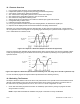
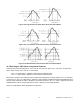
• whether to transmit Alarm 1 or 2 status character [DAT.1]
• whether to transmit peak and valley status character [DAT.2]
• whether or not the data transmitted is filtered or unfiltered [DAT.3 & DAT.4]
• whether or not to transmit the peak and valley readings [DAT.5 & DAT.6]
• the type of separator [DAT.7]
• whether or not to transmit the unit of measure [DAT.8]
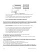
MENU BUTTON
MAIN MENU
MIN/MAX/MENU *
BUTTON SUB MENU
DESCRIPTION
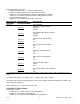
DATA FORMAT
Alarms 1 & 2 Status Character:
“DAT.1=0”
Excluded
“DAT.1=1” Included
HI/LO (Peak/Valley) Status Character:
“DAT.2=0”
Excluded
“DAT.2=1” Included
Filtered Value to be transmitted:
“DAT.3=0” No
“DAT.3=1”
Yes
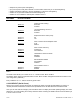
Filtered value to be transmitted:
“DAT.4=0” No
“DAT.4=1” Yes
Peak value to be transmitted:
“DAT.5=0”
No
“DAT.5=1” Yes
Valley value to be transmitted:
“DAT.6=0” No
“DAT.6=1” Yes
Separator for above items:
“DAT.7=0”
Space
“DAT.7=1” <CR>
Unit of measurement to be transmitted:
“DAT.8=0”
No
“DAT FT”:
“DAT.8=1” Yes
* The ‘MIN’ button allows you to sequence through DAT.1, DAT.2, DAT.3, DAT.4, DAT.5, DAT.6, DAT.7, and
DAT.8.
The ‘MAX’ button allows you to select the “0” or “1” state for each “DAT” condition.
The ‘MENU’ button stores the selected values for each “DAT” condition changed and advances the meter to the
next configuration (“BUS FT”).
Every underlined “0” or “1” is the factory preset value.
9.2.22 BUS FT (Bus Format)
Bus format is to select:
• whether or not to include check sum with reading [BUS.1]
• whether or not to include line feeds [BUS.2]
• whether or not to have the meter respond in echo mode [BUS.3]
CF 67 47 M1291/N/0403 11279ML-02 Rev. A