
Instruction Manual

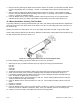
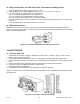
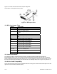
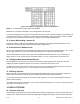
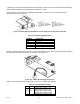
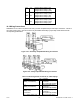


Figure 13-2 shows the board connections and pin designators.
The locations of the jumpers are also shown.
Figure 13-2. BCD Option Board
13.2 BCD Card Jumper Table
JUMPER WHEN USED
S1A Brings OVERFLOW signal to P8-U18
S2A Insert for 3-digit multiplex
Remove for 6-digit readout
S3A Insert for 3-digit multiplex or one-line card-address
enable
OR
S3B 4-line card-address enable
S4A Insert for 3-digit multiplex
OR
S4B Insert for 6-digit readout
S5A P8-U20 must be low to enable card
Remove for high or open enable
S5C P8-L20 must be low to enable card
Remove for high or open enable
S5E P8-U19 must be low to enable card
Remove for high or open enable
S5G P8-L19 must be low to enable card
Remove for high or open enable
S6A, S6B,
S7A, S7B
Install for internal power
Remove for isolated power
S8A Output data is negative-true
OR
S8B Output data is positive-true
13.3 Interconnect Board
For mechanical support and electrical interconnection, each BCD board is shipped with a small 5-pin
INTERCONNECT board. Insert onto the main board pins immediately behind the right-hand side of the display
board. The BCD board itself (component side down) is 13-4 then plugged into the interconnect board at J20, with
the PCB connection fingers protruding from the case rear. For assembly detail, refer to Figure 5-5 (in Section 5).
13.4 50-Line Cable Compatibility
The 40 lines of the BCD connector are compatible with lines 9 through 48 of some 50-line busses (left-most 8 and
right-most 2 are not used by this BCD option).
CF 67 59 M1291/N/0403 11279ML-02 Rev. A