
Instruction Manual

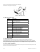
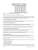


Figure 13-3. Address Programming Chart for 4-line Address
NOTE: “X” in chart indicates jumper that must be installed.
EXAMPLE: For a positive true address of 03, install jumpers S5-G and S5-E.
If any of these jumpers are removed, the corresponding line must go HIGH or OPEN to assist the card enable; if all
four jumpers are missing, for example, the card outputs are enabled ONLY when all four lines are HIGH or OPEN,
a ground on any of the four input lines causes the outputs to go to the high impedance state.
13.11 Select Data Polarity: Jumper S8
Inserting the jumper in S8B (the usual shipping position) makes the output data (including decimal point code)
positive-true. Placing the jumper in S8A converts the data to negative-true.
13.12 Decimal Point Address Code
P8-U15, P8-L8 and P8-U8 output a 3-bit positive-true binary code for the location of the decimal point: “001” for the
extreme right position and “110” for the extreme left position (just to the right of the left-hand digit).
Panel-mounted printers, however, may require an inverted/shifted decimal point code. You can create this by
setting “OUT.5=1” in the “OUT.CNF” byte (unlocked by setting “L1C.7=0”), rather than the normal “OUT.5=0”.
13.13 Applying Non-Isolated/Isolated Power
Non-isolated power from the meter is connected to this board by inserting jumpers S6A, S6B, S7A, and S7B
(bridging the isolation separation distance on the board). Current drawn is less than 10 mA.
To isolate these outputs from the other meter circuits, remove the four jumpers described earlier, and connect an
external, nominal 5 V supply to P8-L17, with its ground return connected to P8-L15.
13.14 Driving A Printer
Direct connection of the 24 BCD lines and the 3 decimal point address lines is all that is needed for positive-true
printers that accept a binary-coded decimal point address (which do not print the decimal point).
If your printer has more than 6 digits, tie the unused inputs to ground or V+ or leave open (whichever produces
blanks in those locations).
For negative-true decimal pint addresses, found in some panel-mounted printers, set “OUT.5=1” (part of menu item
“OUT.CNF”, unlocked by “L1C.7=0”).
14. RELAY OPTIONS
14.1 Features Overview
The Dual Relay Output Board and 4 Relay Output Board provides two isolated (354 v per IEC spacing, 500 test), 7-
ampere Form-C electro-mechanical relays that enable setpoint-triggered switching to an external device (plus two
CF 67 61 M1291/N/0403 11279ML-02 Rev. A