
Instruction Manual


1-ampere Form-C electro-mechanical relays for 4 Relay Option). Each relay can accommodate a single setpoint.
200 W, 2500pf snubbers are provided for each normally open contact.
These options may not be used with parallel BCD Board Option. Figure 14-1 and 14-2 shows the board
connections and jumper locations.
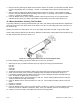
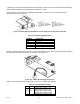
Figure 14-1. Relay Option Board With S1 Jumper Positions and Connection Diagram.
Table 14.1 Dual Relay Board Jumpers
JUMPER FUNCTION
S1A* Drives Relay 1 from SP3 (P6)
S1B not used
S1C Drives Relay 2 from SP2 (P7)
S1D Drives Relay 1 from SP1 (P6)
S1E* Drives Relay 2 from SP4 (P7)
* Factory preset jumper locations
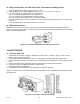
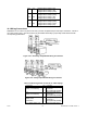
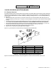
Figure 14-2 below shows the locations of the 4 Relay Output Board jumpers, the P10 plug connecting the board to
the Main Board, and the positions of P6, P7 and P18, the output plugs.
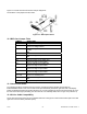
Figure 14-2. 4 Relay Board Jumpers and Plugs.
Table 14-2 shows which jumpers are assigned to each relay. Defaults have asterisks.
Table 14-2. 4 Relay Board Jumpers
S1 S2 Function
A,C*
A,C*
Assigns SP1 to Relay 1 (P6)
Assigns SP2 to Relay 2 (P7)
Assigns SP3 to Relay 3 (P18)
Assigns SP4 to Relay 4 (P18)
Assigns SP1 to Relay 3 (P18)
CF 67 62 M1291/N/0403 11279ML-02 Rev. A