
Instruction Manual


B,D A, C Assigns SP2 to Relay 2 (P7)
Assigns SP3 to Relay 1 (P6)
Assigns SP4 to Relay 4 (P18)
B,D
B,D
Assigns SP1 to Relay 3 (P18)
Assigns SP2 to Relay 4 (P18)
Assigns SP3 to Relay 1 (P6)
Assigns SP4 to Relay 2 (P7)
A,C
B,D
Assigns SP1 to Relay 1 (P6)
Assigns SP2 to Relay 4 (P18)
Assigns SP3 to Relay 3 (P18)
Assigns SP4 to Relay 2 (P7)
14.2 Wiring/Connections
WARNING: Do not connect ac power meter until you have completed all input and output connections. Failure to
do so may result in injury! This device must only be installed electrically by a specially trained electrician with
corresponding qualifications.
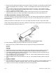
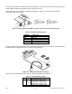
Figure 14-3. Dual Relay Output Board Wiring Connections.
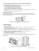
Figure 14-4. 4 Relay Output Board Wiring Connections
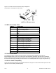
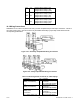
Table 14-3 Pin Assignments for the P6, P7 and P18 plugs
Connector Pin Function
P-6
(Relay 1 Connection)
1
2
3
NO1 (Normally Open)
Common 1
NC1 (Normally Closed)
P-7
(Relay 2 Connection)
1
2
3
NO2 (Normally Open)
Common 2
NC2 (Normally Closed)
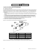
P-18
(Relay 3 & 4
Connection
For 4 Relay Option only.)
1
2
3
4
NO3 (Normally Open)
Common 3
NC3 (Normally Closed)
NO4 (Normally Open)
CF 67 63 M1291/N/0403 11279ML-02 Rev. A