
Instruction Manual

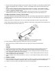
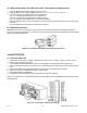
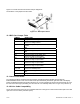
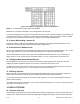
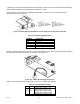
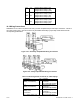
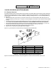


Figure 15-2a. Older RS-232 Option Board Figure 15-2b. Older RS-485 Option Board
and Pin Designations and Pin Designations
15.2 Front-Panel Pushbutton Configuration
Setup configuration can be accomplished via the front panel buttons or via your computer if you use the
configuration setup program. If you are going to use a computer, your choices include “AUTO SET” or “MANUAL
SET” for establishing communication with your meter. “AUTO SET” cycles through the possible combinations of
baud rate, parity and stop bits to find a match for your meter settings. For faster action, you may enter the values
for your meter via “MANUAL SET”.
If your meter communications settings are unknown or need changing, you can insert the factory-set values with
the front panel buttons (or, after communications has been established, from your keyboard).
1. Unlock the communications bits by setting “L4C.1=0”, “L4C.2=0”, “L4C.3=0”, “L4C.4=0” and “L4C.5=0”.
2. Press the ‘MENU’ button until “BAUD” is displayed, then press the ‘MAX’ button until the baud rate you require
is displayed. Press the ‘MENU’ button to store this choice and your meter will display “SERCNF”.
3. Press the ‘MIN’ button until you see the display show “SER.1=0” for no parity, “SER.1=1” for odd parity, or
“SER.1=2” for even parity. Press the ‘MAX’ button to select the parity required for your system. Once you have
done that, press the ‘MIN’ button and advance to “SER.2=0” or “SER.2=1”.
4. By pressing the ‘MAX’ button you can select the “SER.2” value. Setting “SER.2=0” picks the value to one stop
bit; “SER.2=1” selects two stop bits. Select “SER.2=0”.
5. Pressing the ‘MENU’ button stores these choices and then the meter advances to “ADDRES”. Use the ‘MAX’
button to set to “001” (unless your meter is one of several on an RS-485 bus, in which case you must give a
different address to each device and use those addresses when communicating from your computer).
6. Press the ‘MENU’ button again and press the ‘RESET’ button two times to return to the run mode. The
remaining communications format and options are set from your keyboard.
16.0 EXTERNAL CONTROL LINES
P2, the 20-pin connector at the rear of the main board, connects to the setpoint transistor collectors and permits
remote control of significant meter features.
The meter case label gives the names (abbreviated functions) of each of the twenty pins of P2, the center-bottom
connector. Refer to Figure 16-1.
Figure 16-1. Connector Label Detail
CF 67 65 M1291/N/0403 11279ML-02 Rev. A