
Instruction Manual


16.11 Print Command And/Or Reset Of Alarms (PIN 11)
Grounding this pin to P2-7 when “BUS.8=1” has been programmed will initiate a meter printout via serial
communications in the format previously selected. If “ALC.8=1” it causes the alarm latches to reset.
16.12 Nonstandard RX (PIN 12) And Nonstandard TX (PIN 13)
These two pins allow digital communications with the meter using 5 V CMOS logic levels and RS-232 protocols and
format. This access is normally reserved for specialized equipment communication in a calibration lab or at the
factory.
16.13 Push to CAL (PIN 14)
See Section 16.6.
16.14 +V EXT (PIN 15)
This is the pin on which to bring in isolated external 5 to 30 V to power the snubbing diodes of the four
setpoint/alarm open-collector transistors.
16.15 SP1 (PIN 16)
The open-collector of the first setpoint transistor (can carry 150 mA).
16.16 SP2 (PIN 17)
The open-collector of the second setpoint transistor (can carry 150 mA).
16.17 AL1 (PIN 18)
The open-collector of the third setpoint (first alarm) transistor (can carry 150 mA).
16.18 AL2 (PIN 19)
The open-collector of the fourth setpoint (second alarm) transistor (can carry 150 mA).
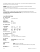
16.19 RTN EXT (PIN 20)
This is the return to the external ground (P2-20) of the external power for the setpoint transistors and snubbing
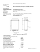
diodes brought in on P2-15, 16, 17, 18 and 19. Figure 16-2 shows an example of a circuit using an external relay
with SP1 (Setpoint 1). If a solid-state relay is used, delete connection to Pin 15.
Figure 16-2. Connection of External Power for Setpoint Transistors
17.0 TROUBLESHOOTING - DISPLAY MESSAGES AND TROUBLESHOOTING
GUIDE
A flashing alpha-numeric message in the display generally indicates an incorrect combination of jumpers and/or
configuration values.
CF 67 67 M1291/N/0403 11279ML-02 Rev. A