
Instruction Manual


• Unit mounting should allow for adequate ventilation to ensure instrument does not exceed operating
temperature rating.
Use electrical wires with adequate size to handle mechanical strain and power requirements. Install without
exposing bare wire outside the connector to minimize electrical shock hazards.
EMC Considerations
• Whenever EMC is an issue, always use shielded cables.
• Never run signal and power wires in the same conduit.
• Use signal wire connections with twisted-pair cables.
• Install Ferrite Bead(s) on signal wires close to the instrument if EMC problems persist.
Failure to follow all instructions and warnings may result in injury!
4.0 PARTS OF THE METER
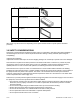
4.1 Front Of The Meter
The following is a brief description of each part of the front of the meter.
Figure 4-1. Front Detail
ITEM DESCRIPTION
1
.8.8.8.8.8. or 8.8.8.8.8.8.
6-digit, 14 segment, alphanumeric 0.54" high
LED display with programmable decimal point.
2
SETPOINT LED
These LEDs, labeled 1 through 4, display the status of setpoints 1, 2, 3 (Alarm 1), and 4 (Alarm 2).
3
SETPTS BUTTON
This button functions only in the run mode. When the Setpoint/Alarm features are unlocked, pressing this
button sequentially recalls the previous setpoint settings to the display. After the ‘ /MIN’ and ‘_/MAX’ buttons
are used to alter those values as desired, pressing the ‘SETPTS’ button, again, stores these new values.
Unless the ‘SETPTS’ button is pressed, each of the four setpoint values is displayed for approximately 10
seconds after the last press of the ‘SETPTS’ button. Holding the ‘SETPTS’ button depressed stalls this
automatic sequence, retaining the most recent setpoint number on the display.
CF 67 4 M1291/N/0403 11279ML-02 Rev. A