
Owner's manual

4
DFI Infinity-Using This Quick Start Manual
Use this Quick Start Manual to get your High Performance
Strain Gage Indicator up and running right out of the box.
These instructions use the factory default settings of 100mV
unipolar input and 10 Vdc sensor excitation. If you have
voltage or current input, refer to the main manual. To start your
unit:
¥ Connect ac power
¥ Wire the sensor
¥ Configure the meter, using the front panel buttons and the
configuration menus
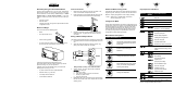
Before You Begin
Your unit should have the following parts:
¥ Meter
¥ Front panel button cover
¥ Panel mounting gaskets
¥ ac Power Connector (orange -P1), Input Connectors (2)
(P3 and P9), and rear protective cover (mounted).
Contact the Customer Service Department using
the number listed on the front of this manual if any of these
parts are missing, or if you have questions.
In addition to the unit and related parts, you will need the
following items to set up your unit:
¥ ac power as listed on meterÕs product/ID label
¥ External sensor (e.g.; load cell)
¥ 1/8Ó Phillips head screwdriver
¥ 1/8Ó flat blade screwdriver
1
2
3
P3
1
2
3
P9
1
2
3
P1
N
L
©
Key Sequences and Menus
MENU key Sub Menu 1
MENU key Submenu 1 Action/Description
(䊳/MIN)
L1CNF
Skip past
L2CNF
Skip past
L3CNF
Skip past
L4CNF
Skip past
INPUT bridge
Select meter input
Sub Menu 1 choice (BRIDGE)
RDG.CNF RDG.1=0
Scaling y = mx+b
RDG.2=0
Active decimal point
RDG.3
=
0
Normal display brightness
RDG.4
=
1
Leading zeroes suppressed
RDG.5
=
0
Not used, skip past
RDG.6
=
1
Activates RDG SC/OF
RDG.7
=
0
External hard reset vs peak reset
RDG SC
See previous formula in
"Determine Meter Scaling Factor"
section.
RDG OF 000000
INCNF INP.1
=
0
60 Hz ac power
INP.2
=
0
Slow reading
(S1A jumper omitted)
INP.3
=
0
Unipolor input
(S1B jumper omitted)
INP.4
=
0
Std, for BRIDGE inputs
INP.5
=
0
Not used, skip past
INP.6
=
0
Disables IN.SC.OF
(Input Scale and Offset)
INP.7
=
1
Ratiometric input
IN.SC.OF
Skip past
DEC PT FFFF.FF
Select decimal point
CNT BY
Press RESET twice
Now you are in RUN mode. If the meter does not read zero,
refer to ÒConfigure Reading OffsetÓ section.
Determine Meter Scaling Factor
Calculate the scaling factor so the meter displays the desired
engineering units. Assuming no known load, use the formula:
RDG SC = display span/[(sensorÕs mV/V output) (10,000)]
where: display span = desired display at full scale
sensorÕs output span = mV/V
Configure the Meter
Use the front panel buttons to access the configuration menus,
to either verify or set the unit values. The first table that follows
describes functions of each button on the front of the meter.
The second table summarizes the key sequences you must
press and the menus you will see to get your meter running.
For a step-by-step procedure of specific tasks, refer to the
configuration sections following the tables.
Meter Button Descriptions
Press This Button To:
Access the configuration program
menus and move from one menu
to the next.
Enter and scroll through a
submenu.
Change the value of a submenu.
Move backward one menu (press
once), or exit the configurations
menus (press twice).
Change the Setpoints.
SETPTS
RESET
䊱/MAX
䊳/MIN
MENU
Connect ac Power
1. Remove the rear protective cover and set it aside. The
cover is secured with a Phillips-head screw.
2. Locate connector P1 on the bottom-left-rear of the unit. The
connector has three screw-down terminals (see below).
3. Insert the correct wire in each terminal and tighten the
lockdown screw. Tug gently on each wire to verify the
connection.
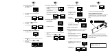
Wiring a Millivolt Output Sensor
The following example shows wiring a bridge input to the meter.
1. Locate connectors P3 and P9 on the right-side rear of the
unit.
2. Attach the wires and tighten the retaining screws. Tug
gently on the wires to verify the connection.
Wiring Example (Factory set at 10Vdc Excitation
3. Apply ac power. The front panel of the unit flashes
RESET2
. If it does not:
a. Remove ac power.
b. Verify the P1 power and sensor connections.
c. Check your power source.
d. Apply ac power again.
4. Replace the rear cover. Thread the sensor wires through
the slots on the side of the cover. Replace the rear cover
retaining screw.
METER
NC
NC
+
E
+
S
–
S
–
E
P9
P3
1
2
3
1
2
3
+
EXC
+
SIG
–
SIG
–
EXC
~AC LINE
~AC NEUTRAL
~AC EARTH GROUND
1
2
3
P1
N
L
START HERE
2
3
GASKET