Model 3i DIGITAL FORCE / TORQUE INDICATOR User’s Guide
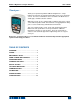
Model 3i Digital Force/Torque Indicator User’s Guide Thank you… Thank you for purchasing a Mark-10 Model 3i digital force / torque indicator, designed for use with interchangeable remote force and torque sensors. A 3i-sensor combination can be used with some Mark-10 test stands grips, and data collection software. With proper usage, we are confident that you will get many years of great service with this product.
Model 3i Digital Force/Torque Indicator User’s Guide 1 OVERVIEW 1.1 List of included items Qty. 1 1 1 1 1 1 Part No. 12-1049 08-1022 08-1026 09-1165 - Description Carrying Case AC adapter body with US, EU, or UK prong Battery (inside the indicator) Certificate of conformance USB cable Resource CD (USB driver, user’s guides, MESURTM Lite software, MESURTMgauge DEMO software, User’s Guide) 1.
Model 3i Digital Force/Torque Indicator User’s Guide Example 1 Model MR50-50Z sensor with Model M3i Indicator MR50-50Z ±0.35% of full scale + M3i ±0.2% of full scale ±1 digit = Total ±0.55% of full scale ±1 digit This translates into a fixed error of up to: 0.55% x 50 ozFin = 0.275 ozFin + 0.02 ozFin = 0.295 ozFin Example 2 Model MR01-100 sensor with Model M5i Indicator MR01-100 ±0.15% of full scale + M5i ±0.1% of full scale ±1 digit = Total ±0.
Model 3i Digital Force/Torque Indicator User’s Guide testing, especially in aforementioned hazardous cases. Extra bodily protection should be worn if a destructive failure of a test sample is possible. 9. In aforementioned hazardous situations, it is strongly recommended that a machine guarding system be employed to protect the operator and others in the vicinity from shards or debris. 10. Sensors have threaded holes or chucks, designed for the mounting of grips, fixtures, or attachments.
Model 3i Digital Force/Torque Indicator User’s Guide The indicator can be configured to automatically power off following a period of inactivity. Refer to the Other Settings section for details. If battery replacement is necessary, the battery may be accessed by loosening the two captive screws in the rear half of the housing and separating the two halves of the housing. 3 MECHANICAL SETUP 3.
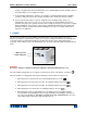
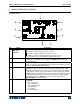
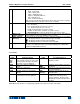
Model 3i Digital Force/Torque Indicator User’s Guide 4 HOME SCREEN AND CONTROLS 4.1 Home Screen 1 9 2 8 3 4 7 6 No. 1 Name Measurement direction indicator 2 Peaks 3 Primary reading 4 Load bar 5 Units 5 Description – indicates compression direction (for force sensors) – indicates tension direction (for force sensors) – indicates clockwise direction (for torque sensors) – indicates counter-clockwise direction (for torque sensors) These indicators are used throughout the display and menu.
Model 3i Digital Force/Torque Indicator 6 Mode 7 Battery / AC adapter indicator High / low limit indicators 8 9 Set points User’s Guide Torque units: lbFin – Pound-inch ozFin – Ounce-inch kgFm – Kilogram-meter kgFmm – Kilogram-millimeter Nm – Newton-meter Ncm – Newton-centimeter Note: not all sensor models display all the above units. Refer to the capacity / resolution table for the respective sensor series for details. The current measurement mode.
Model 3i Digital Force/Torque Indicator User’s Guide 4.3 Menu navigation basics Most of the indicator’s various functions and parameters are configured through the main menu. To access the menu press MENU. Use the UP and DOWN keys to scroll through the items. The current selection is denoted with clear text over a dark background. Press ENTER to select a menu item, then use UP and DOWN again to scroll through the sub-menus. Press ENTER again to select the sub-menu item.
Model 3i Digital Force/Torque Indicator User’s Guide 6 CHANGING THE UNITS The 3i can display several measurement units, depending on the sensor. To change the unit, select Units from the menu. The display will list the available units, for example: UNITS * lbF kgF N The indicator will always power on with the unit selected. 7 DIGITAL FILTERS Digital filters are provided to help smooth out the readings in situations where there is mechanical interference in the work area or test sample.
Model 3i Digital Force/Torque Indicator User’s Guide SET POINTS Upper Disabled * Upper Enabled 5.00 Lower Disabled * Lower Enabled 3.50 Either one, two, or none of the set points may be enabled. To toggle between the tension and compression (or clockwise and counter-clockwise) directions, press the DIRECTION key. If two set points have been enabled, they are displayed in the upper left corner of the display. If only one set point has been enabled, the word “OFF” will appear in place of the value.
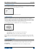
Model 3i Digital Force/Torque Indicator User’s Guide or Click “Install”. 3. The next screen appears as follows: Click “Continue Anyway”. 4. After installation completes the following screen may appear in non-Windows 7 operating systems. Restart the computer before connecting a Mark-10 USB device. 5. After Windows as restarted, plug in the device. The following will occur: Windows 7 Operating Systems – When the Mark-10 USB device has been plugged into a USB port, the driver will automatically be found.
Model 3i Digital Force/Torque Indicator User’s Guide Select “No, not this time”, then click “Next”. 6. The next screen appears as follows: Select “Install the software automatically (Recommended)”, then click “Next”. 7. The next screen appears as follows: Click “Continue Anyway”.
Model 3i Digital Force/Torque Indicator User’s Guide 8. The next, and final, screen appears as follows: Click “Finish”. The Mark-10 USB device is now installed and ready to use. The COM port number assigned by Windows may be identified in Device Manager, or in the communication application being used, such as MESURgauge or HyperTerminal. 9.2 Communication Settings To set up communication settings, select USB Settings from the menu.
Model 3i Digital Force/Torque Indicator User’s Guide 10.2 Calibration Procedure In the interests of simplicity and brevity, the following instructions use force terminology only. Such wording is displayed only when a force sensor is being calibrated. When a torque sensor is being calibrated, the terms COMPRESSION and TENSION are replaced by CLOCKWISE and COUNTERCLOCKWISE, respectively. 1. Select Calibration from the menu.
Model 3i Digital Force/Torque Indicator User’s Guide CALIBRATION OFFSET Please wait… CALIBRATION OFFSET CALIBRATION OFFSET Sen.Offset Adj.Passed Ana.Offset Adj.Passed Sen.Offset Adj.Failed Ana.Offset Adj.Failed If failed: 5. The following screen appears after the offsets have been calculated: CALIBRATION COMPRESSION Attach necessary weight fixtures. THEN PRESS ENTER Attach weight fixtures (brackets, hooks, etc), as required. Do not yet attach any weights or apply any calibration loads.
Model 3i Digital Force/Torque Indicator User’s Guide CALIBRATION COMPRESSION ENSURE NO LOAD THEN PRESS ZERO Remove the load applied in Step 8, leave the fixtures in place, then press ZERO. 9. The display will appear as follows: CALIBRATION COMPRESSION APPLY LOAD 1 OF 5 ENTER LOAD: 2.000 LBF THEN PRESS ENTER Use the UP and DOWN keys to adjust the load value as required.
Model 3i Digital Force/Torque Indicator User’s Guide CALIBRATION Units must be gF. PLEASE TRY AGAIN PRESS ENTER Displayed at the start of calibration if a disallowed unit is selected. LOAD NOT STABLE PLEASE TRY AGAIN Ensure that the load is not swinging, oscillating, or vibrating in any manner. Then try again. CALIBRATION COMPRESSION LOAD TOO LOW PLEASE TRY AGAIN The calibration weight does not match the set value.
Model 3i Digital Force/Torque Indicator User’s Guide AUTOMATIC SHUTOFF * Disabled Enabled Set Minutes 5 Select Disabled to disable automatic shutoff. Select Enabled to enable it. The length of time of inactivity is programmed in minutes via the Set Minutes parameter. Available settings: 5-30, in 5 minute increments. Note: If the AC adapter is plugged in, the indicator will ignore these settings and remain powered on until the POWER key is pressed. 11.
Model 3i Digital Force/Torque Indicator User’s Guide 11.4 Beeps Audible tones can be enabled for all key presses and alerts, such as overload, set point value reached, etc. The Set Point alert can be configured to be either a momentary tone or a continuous tone (until the load is restored to a value between the set points). To configure the functions for which audible tones will apply, select Beeps from the menu. The screen will appear as follows: BEEPS Keys * Alerts Set Points * Momentary Continuous 11.
Model 3i Digital Force/Torque Indicator User’s Guide 12 SPECIFICATIONS 12.1 General Accuracy: Sampling rate: Power: Battery life: ±0.2% of full scale ±1 digit + sensor 2,000 Hz AC or rechargeable battery. Low battery indicator appears when battery level is low, and indicator powers off automatically when power reaches critical stage.
Model 3i Digital Force/Torque Indicator User’s Guide 12.
Model 3i Digital Force/Torque Indicator User’s Guide NOTES: 22
Model 3i Digital Force/Torque Indicator User’s Guide Mark-10 Corporation has been an innovator in the force and torque measurement fields since 1979. We strive to achieve 100% customer satisfaction through excellence in product design, manufacturing and customer support. In addition to our standard line of products we can provide modifications and custom designs for OEM applications. Our engineering team is eager to satisfy any special requirements.