
User guide
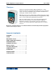


Model 3i Digital Force/Torque Indicator User’s Guide
5
The indicator can be configured to automatically power off following a period of inactivity. Refer to the
Other Settings section for details.
If battery replacement is necessary, the battery may be accessed by loosening the two captive screws in
the rear half of the housing and separating the two halves of the housing.
3 MECHANICAL SETUP
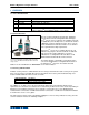
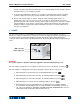
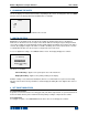
3.1 Connecting a sensor
The Plug & Test
TM
connector must be inserted into the receptacle of the 3i or 5i indicator with the side
marked “Plug & Test
TM
Technology” facing up (see Fig. 3.1). When fully inserted, the connector will lock
into place with a “click”.
Fig. 3.1
Appropriate orientation of Plug & Test
TM
connector.
Sensor model number, serial number, and load
capacity information may be found on the labels
affixed to the connector.
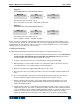
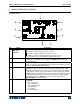
To release the connector, press both buttons on either side of the indicator housing to release the sensor
(see Fig. 3.2). Pull the connector completely out of the indicator by holding the curved aluminum section.
DO NOT pull on the cable or strain relief.
Fig. 3.2
Press both buttons on either side of the indicator
housing to release the Plug & Test
TM
connector.
3.2 Mounting to a plate
The 3i can be mounted to a plate with four thumb screws fastened into the appropriate holes in the rear
half of the housing. Refer to the Dimensions section for detailed hole information and locations.