
User guide


Model 3i Digital Force/Torque Indicator User’s Guide
6
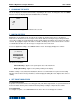
4 HOME SCREEN AND CONTROLS
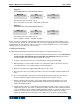
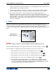
4.1 Home Screen
No. Name Description
1 Measurement
direction
indicator
– indicates compression direction (for force sensors)
– indicates tension direction (for force sensors)
– indicates clockwise direction (for torque sensors)
– indicates counter-clockwise direction (for torque sensors)
These indicators are used throughout the display and menu.
2 Peaks
The maximum measured compression/tension or clockwise/counter-clockwise
readings. These readings are reset by pressing ZERO or by powering the
indicator off and on.
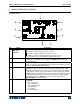
3 Primary reading
The current displayed load reading. See Operating Modes section for
details. If a sensor is not plugged in, this value will be replaced by a message,
as follows: SENSOR NOT CONNECTED
4 Load bar
Analog indicator to help identify when an overload condition is imminent. The
bar increases either to the right or to the left from the midpoint of the graph.
Increasing to the right indicates compression or clockwise load, increasing to
the left indicates tension or counter-clockwise load. If set points are enabled,
triangular markers are displayed for visual convenience. This indicator reflects
the actual load, which may not correspond to the primary reading (depends
on operating mode). The ZERO key does not reset the load bar. See
Operating Modes section for details.
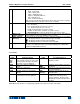
5 Units
The current measurement unit. Abbreviations are as follows:
Force units:
lbF – Pound-force
ozF – Ounce-force
kgF – Kilogram-force
gF – Gram-force
N – Newton
kN – Kilonewton
1
2
4
56
7
8
9
3