
Owner manual


Series 7 Digital Force Gauges User’s Guide
31
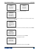
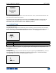
10. The display appears as follows:
Use the UP and DOWN keys to adjust the load value as required. The load values default to even
increments, as indicated by the previously entered number of data points (even increments are
recommended for best results). For example, if a 50 lbF capacity gauge is calibrated, and 5 data
points were selected, the load values will default to 10, 20, 30, 40, and 50 lb. Apply the calibration
load. Then press ENTER.
Repeat the above step for the number of data points selected.
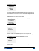
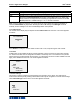
11. After all the compression calibration points have been completed, the display appears as follows:
Press ENTER.
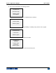
12. The display appears as follows:
Reverse the orientation of the load cell shaft by rotating the gauge 180 degrees. Press
DIRECTION to invert the display. Then attach weight fixtures. The following screens will step
through the same procedure as with the compression direction. Proceed in the same manner.
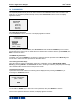
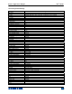
13. At the completion of the tension calibration, the display appears as follows:
To save the calibration information, select “Save & exit”. To exit without saving the data select
“Exit without saving”.
CALIBRATION
To invert the
display, press the
DIRECTION button,
then press ENTER
CALIBRATION
COMPLETE
Save & exit
Exit w/o saving
CALIBRATION
COMPRESSION COMPLETE
Reverse direction
for tension.
Attach necessary
weight fixtures,
then
p
ress ENTER.
CALIBRATION
COMPRESSION
Apply load
1 OF 5
Enter load:
2.000 lbF
Press ENTER.