
Instruction Manual

MODELS
XC – with compression calibration
XST – with tension calibration
XPP - with compression/tension calibration
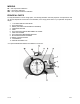
PRINCIPAL PARTS
For easy identification of Force Gauge parts*, the following illustration has been prepared. Correspondence with
our Service Department should refer to this illustration, and a rough pencil sketch of your particular setup will be
helpful.
1. “U” SHAPED DEFLECTION BEAM
2. DIAL INDICATOR
3. BEZEL (FOR ZERO ADJUSTMENT PURPOSES)
4. PRESSURE BUTTON
5. ANVIL
6. DIAL INDICATOR GAUGE MOVEMENT PLUNGER
7. ANVIL SET SCREW
8. DIAL INDICATOR MOUNTING BRACKET
9. MOUNTING BRACKET SCREWS
10. BEZEL LOCKING SCREW
11. LOADING BALL
12. SPRING RETAINER CLIP
* An optional MAXIMUM POINTER is available but not shown.
CF 109 1 11/02