
Programming Manual
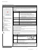
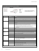
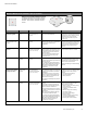
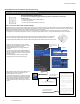
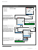
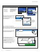
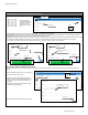

Table Of Contents
- Becoming Familiar with WaveLinx System Components
- WaveLinx Device Reference Sheets
- WaveLinx Wireless Area Controller 2 (Gen 2)
- WaveLinx Wireless Area Controller (Gen 1)
- Ambient Integrated Sensor Reference Sheet
- Industrial Integrated Sensor Reference Sheet
- Outdoor Integrated Sensor Reference Sheet
- Outdoor Sensor Extender/Multiplier Reference Sheet
- Wireless Tilemount Sensor Reference Sheet
- WaveLinx Outdoor Lighting Control Module
- WaveLinx Wireless Fixture Reference Sheet
- WaveLinx Universal Voltage Dimming Switchpack
- WaveLinx Universal Voltage Dimming Switchpack with Emergency
- WaveLinx Universal Voltage Dimming Switchpack with Dry Contact Input
- WaveLinx Low-Voltage Power Module
- Low-Voltage Fixture with Integrated Sensor Reference Sheet
- Low-Voltage Fixture
- WaveLinx Receptacle
- WaveLinx Ceiling Sensor
- WaveLinx Wallstation
- WaveLinx Battery Powered Wallstation
- WaveLinx Touchscreen
- ISHH-01 Integrated Sensor Programming Remote
- WaveLinx Device Reference Sheets

WaveLinx User Manual
20
www.cooperlighting.com
WaveLinx Wireless Area Controller (Gen 1)
WaveLinx Wireless Area Controller (Gen 1)
Features
• Coordinates communication between
WaveLinx Devices and the Mobile App
• Optionally connects to Trellix Core for
use with:
• Trellix Applications
• BMS,
• Other Third-Party systems.
Power:
• Powered from PoE or PoE Injector
Typical Applications
• Required for communication to
WaveLinx Devices
Models:
WAC: Wireless Area Controller
Mobile App Details:
• Default Device Name:
• CooperWAC-XX-XX
Icon Displayed in Mobile App:
The Wireless Area Controller (WAC) is the central communications coordinator for the WaveLinx system. A
Wireless Area Controller (Gen 1) can coordinate communication to up to 150 devices within its wireless
range (for best performance, connect up to 100 devices).
The Wireless Area Controller can operate as a stand-alone coordinator or may be connected to a building
network with other Wireless Area Controllers to meet larger building requirements.
WAC (Gen 1) Details
Feature Details
Supported Devices The WAC (Gen 1) supports up to 150 WaveLinx Devices (for best
performance, connect up to 100 devices).
• All devices may be WaveLinx Wireless Devices OR
• Up to 100 of the devices may be WaveLinx Low Voltage
• Example: 100 Low-Voltage = 100 Devices
• Up to 50 of the devices may be actively using RTLS functionality
• Example: 50 RTLS Devices + 50 WaveLinx Wireless = 100 Devices
• Example: 50 RTLS Devices +40 Low-Voltage + 10 WaveLinx Wireless
= 100 Devices
Areas The WAC (Gen 1) supports up to 16 areas.
• 15 user defined areas plus 1 default construction area.
Zones
• The WAC (Gen 1) creates two default dimming zones per area (Zone 1 and
Zone 2), and one default receptacle zone per area (Zone 3).
• The WAC (Gen 1) supports up to 16 zones per area.
Scenes
The WAC (Gen 1) supports up to 16 scenes per area.
Occupancy Sets
The WAC (Gen 1) supports up to 6 occupancy sets per area.
Open Loop Daylight Sets
The WAC (Gen 1) supports up to 6 open loop daylight sets per area.
Out-of-the-Box
• Once power is applied, after approximately 1-2 minutes, the blue power/health LED on top of the unit and
the 802.15.4 LED should illuminate.
3
Loss of Communications Operation
Please refer to the device reference sheets for the devices in the facility for the expected behavior upon loss
of communications with the Wireless Area Controller.
Operation upon Return of Power
Upon return of power, after approximately a 1-2-minute power up period, the Wireless Area Controller will
begin re-establishing connection with controlled devices. This process may take several minutes depending
on the quantity of devices being controlled. Controlled devices will remain in their return of power state until
the connection is re-established.
How to Place in Pairing Mode:
Method Description
PAIR button Press and release (1 second press)
the PAIR button located on the rear
panel of the Wireless Area Controller.
Mobile App
• Login to the Wireless Area Controller.
• From the menu, select ‘Devices’.
• With the Wireless Area Controller selected, tap ‘Actions’ or locate the actions
bar at the bottom of the mobile device screen.
• Select ‘Enable Discover Devices’.
The blue 802.15.4 LED on the Wireless Area Controller will blink at a rate of one blink per second to indicate
the Wireless Area Controller is in pairing mode.
The Wireless Area Controller pairing mode automatically times-out after 60 minutes or can be manually
exited by pressing and releasing (1 second press) the PAIR button or by selecting ‘Disable Discover Devices’
from the Mobile App.
3
The green LAN LED may also illuminate if the controller is connected to a building LAN with a DHCP server. Other LEDs should remain OFF.