
Programming Manual
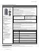
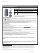
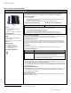
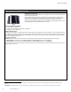
Table Of Contents
- Becoming Familiar with WaveLinx System Components
- WaveLinx Device Reference Sheets
- WaveLinx Wireless Area Controller 2 (Gen 2)
- WaveLinx Wireless Area Controller (Gen 1)
- Ambient Integrated Sensor Reference Sheet
- Industrial Integrated Sensor Reference Sheet
- Outdoor Integrated Sensor Reference Sheet
- Outdoor Sensor Extender/Multiplier Reference Sheet
- Wireless Tilemount Sensor Reference Sheet
- WaveLinx Outdoor Lighting Control Module
- WaveLinx Wireless Fixture Reference Sheet
- WaveLinx Universal Voltage Dimming Switchpack
- WaveLinx Universal Voltage Dimming Switchpack with Emergency
- WaveLinx Universal Voltage Dimming Switchpack with Dry Contact Input
- WaveLinx Low-Voltage Power Module
- Low-Voltage Fixture with Integrated Sensor Reference Sheet
- Low-Voltage Fixture
- WaveLinx Receptacle
- WaveLinx Ceiling Sensor
- WaveLinx Wallstation
- WaveLinx Battery Powered Wallstation
- WaveLinx Touchscreen
- ISHH-01 Integrated Sensor Programming Remote
- WaveLinx Device Reference Sheets

WaveLinx User Manual
36
www.cooperlighting.com
Wireless Tilemount Sensor continued
Daylight Operation for Tilemount Sensors Connected to WaveLinx Control Modules (closed loop)
• Once assigned to an area and enabled (daylight operation is enabled automatically if paired with WAC Gen 1), the
sensor will begin closed loop daylight dimming operation to a reasonable light level. If a specific light level (target) is
expected at the surface, then calibration is required.
• When the measured light exceeds the calibrated level, the connected fixture(s) will dim lighting to reduce the light level.
• When the measured light level exceeds 150% of the calibrated light level for more than 30 minutes, the sensor will dim
to OFF.
• Lighting will be turned back ON when one of the two conditions occurs:
• The measured light level falls between 100% and 50% of the calibrated light level for more than 10 minutes
• The measured light level falls below 50% of the calibrated light level for longer than 30 seconds
Daylight Calibration Details for Tilemount Sensors Connected to WaveLinx Control Modules
The sensor should be mounted where it can view the reflected light level from the surface including light contributed by the electric lighting it controls and the
daylight that falls within the sensor’s view.
It is best to calibrate indoor applications when there is a moderate to low level of daylight. If the daylight level is too high, it may be difficult to obtain the
desired level of light at the task surface, even if the fixtures are completely off.
During calibration, use the ‘Calibrate All’ feature and adjust slider bars to change the light level to the desired light level for each controlled fixture. Once all
fixtures are adjusted, use a light meter on the surface to ensure the reading is in the desired range and then send the ‘Calibrate’ command.
If the light level in the space is still too bright when electric lighting is fully dimmed, use available shading to adjust the amount of incoming daylight or
postpone calibration until the amount of incoming daylight has decreased.
Special Consideration for Tilemount Sensors Connected to a Power Supply
If using Occupancy Sensor functionality:
• Create the necessary control zones in the area and assign the appropriate control devices.
• Identify the Tilemount Sensors and assign them to the correct zone.
• Ensure that the zone is assigned for control from the occupancy set (see page 125).
If using for RTLS functionality:
51
• Create the necessary control zones in the area and assign the appropriate control devices.
• Identify the Tilemount Sensors and assign them to the area or, if desired, to a zone in the area.
• If not using the occupancy sensor functions, ensure that the occupancy sensor is ‘disabled’ to prevent the sensor from operating the area’s lighting (see
page 127).
Factory Reset Instructions
CAUTION: The factory reset will set the device back to factory settings (out-of-the-box behavior) removing pairing and programmed settings.
• Cycle the power to (switch OFF 4 seconds and then ON 4 seconds) the device’s power circuit six times.
This removes pairing for ALL devices of this type on the affected circuit. After a short period of time, the device should exhibit out-of-the-box behavior and
may be paired as a new device.
52
51
RTLS capability may require additional license or firmware purchase.
52
The device may flash the light to indicate the reset was successful. If the light was ON prior to the reset, the light will flash twice then remain ON. If OFF prior to reset, the
flash behavior may not be observed, but lighting will turn ON.