
Programming Manual
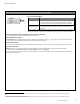
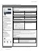
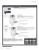
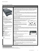
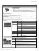
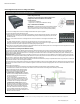
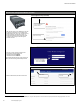
Table Of Contents
- Becoming Familiar with WaveLinx System Components
- WaveLinx Device Reference Sheets
- WaveLinx Wireless Area Controller 2 (Gen 2)
- WaveLinx Wireless Area Controller (Gen 1)
- Ambient Integrated Sensor Reference Sheet
- Industrial Integrated Sensor Reference Sheet
- Outdoor Integrated Sensor Reference Sheet
- Outdoor Sensor Extender/Multiplier Reference Sheet
- Wireless Tilemount Sensor Reference Sheet
- WaveLinx Outdoor Lighting Control Module
- WaveLinx Wireless Fixture Reference Sheet
- WaveLinx Universal Voltage Dimming Switchpack
- WaveLinx Universal Voltage Dimming Switchpack with Emergency
- WaveLinx Universal Voltage Dimming Switchpack with Dry Contact Input
- WaveLinx Low-Voltage Power Module
- Low-Voltage Fixture with Integrated Sensor Reference Sheet
- Low-Voltage Fixture
- WaveLinx Receptacle
- WaveLinx Ceiling Sensor
- WaveLinx Wallstation
- WaveLinx Battery Powered Wallstation
- WaveLinx Touchscreen
- ISHH-01 Integrated Sensor Programming Remote
- WaveLinx Device Reference Sheets

WaveLinx User Manual
42
www.cooperlighting.com
WaveLinx Universal Voltage Dimming Switchpack with Emergency
WaveLinx Universal Voltage Dimming Switchpack with Emergency
General Features
• Universal voltage input (120V-347V)
• Output control (120V-347V):
• Electronic ballast/driver 16A
• General purpose (receptacle) 20A
• Motor loads up to 1.5 HP (120VAC)
• Class 2, 0-10V dimming output
• Sinks up to 120mA (approximately 60
ballasts/drivers [2mA each])
• IEEE 802.15.4, (router and end point)
Special Features
• UL924 approved control of Emergency
Lighting
Typical Applications
• Emergency fixture control
• Office, education, and other indoor
applications
Models:
• WSP-UV-010-EM: Wireless Universal
Voltage Dimming Switchpack with
Emergency
Mobile App Details:
• Default Device Name:
• Relay Switchpack Emergency
• Unassigned Device Category:
• Relay Switch Pack
Icon Displayed in Mobile App:
Use the WaveLinx Universal Voltage Dimming Switchpack with Emergency to wirelessly control Emergency
lighting, including switched or 0-10V emergency lighting loads.
Out-of-the-Box Operation
Once power is applied:
• Connected loads will turn ON and 0-10V dimmable loads will go to 100%.
61
• Onboard commissioning button can be pressed (less than 4 seconds) to turn load OFF and ON.
• White LED on switchpack indicates load state.
Construction Area Default Operation Assigned to an Area Default Operation
Once paired, the device operates as part of the
Construction Area.
Once assigned to a created area, the device
operates as part of the area.
• It will respond to the occupancy set from any occupancy sensors in the area.
• If occupied, the fixtures will turn ON to 50% (Scene 3).
• The occupancy set default hold time is 20 minutes.
• If the space remains unoccupied for 20 minutes, the fixture will dim to 0% (Scene 0).
• It will respond to any wallstations in the area per the default wallstation programming.
Loss of Communications Operation
If the device has not communicated with the Wireless Area Controller for longer than approx.15 minutes, it
will revert to its out-of-the-box behavior until communications are re-established.
Emergency Mode Operation & Operation upon Return of Power
To ensure proper operation for Emergency Mode:
• The WSP-UV-010-EM MUST be wired to an emergency circuit
• The paired Wireless Area Controller MUST be powered from a normal circuit. Do not place the Wireless
Area Controller on a UPS backup or other emergency backup power supply.
If the WSP-UV-010-EM loses power for more than 30 milliseconds, the device will turn ON to 100% output.
The switchpack will ignore all WaveLinx system messages for 20 seconds and then will try to communicate
with the Wireless Area Controller. The switchpack will remain in Emergency Mode until communications are
re-established. It will then go to the last known light level and resume normal operation.
LED Operation
LED conditions Meaning
ON (white)
The device relay is closed
OFF
The device relay is opened
Flashes ON and OFF
approximately 1 time per
second for 10 seconds
Onboard commissioning button has been pressed for longer than 4 seconds,
placing the device in pairing mode.
61
Devices with older firmware may go to 75% light output in out-of-the-box operation and may take up to 1 hour to enter loss of communication operation.