
Programming Manual
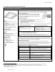
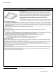
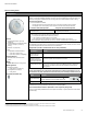
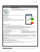
Table Of Contents
- Becoming Familiar with WaveLinx System Components
- WaveLinx Device Reference Sheets
- WaveLinx Wireless Area Controller 2 (Gen 2)
- WaveLinx Wireless Area Controller (Gen 1)
- Ambient Integrated Sensor Reference Sheet
- Industrial Integrated Sensor Reference Sheet
- Outdoor Integrated Sensor Reference Sheet
- Outdoor Sensor Extender/Multiplier Reference Sheet
- Wireless Tilemount Sensor Reference Sheet
- WaveLinx Outdoor Lighting Control Module
- WaveLinx Wireless Fixture Reference Sheet
- WaveLinx Universal Voltage Dimming Switchpack
- WaveLinx Universal Voltage Dimming Switchpack with Emergency
- WaveLinx Universal Voltage Dimming Switchpack with Dry Contact Input
- WaveLinx Low-Voltage Power Module
- Low-Voltage Fixture with Integrated Sensor Reference Sheet
- Low-Voltage Fixture
- WaveLinx Receptacle
- WaveLinx Ceiling Sensor
- WaveLinx Wallstation
- WaveLinx Battery Powered Wallstation
- WaveLinx Touchscreen
- ISHH-01 Integrated Sensor Programming Remote
- WaveLinx Device Reference Sheets

WaveLinx User Manual
www.cooperlighting.com
55
WaveLinx Receptacle
WaveLinx Receptacle
Features
• Top outlet is wirelessly controlled
through WaveLinx while bottom outlet
remains constantly powered
• IEEE 802.15.4, (router and end point)
• Input/Output 120VAC
• WR-15: 15A
• WR-20: 20A
Typical Applications
• Education, office, and other interior
spaces
Models:
• WR-15: WaveLinx Receptacle 15A
• WR-20: WaveLinx Receptacle 20A
Mobile App Details:
• Default Device Name:
• Receptacle
• Unassigned Device Category:
• Receptacle
Icon Displayed in Mobile App:
The WaveLinx Receptacle enables energy savings by turning OFF the top outlet when the area is unoccupied
or with other programmed actions, simplifying plug load control requirements. The bottom outlet remains
constantly powered.
Out-of-the-Box Operation
• Once power is applied, the wirelessly controlled outlet will turn ON.
• LED will illuminate green to indicate that the controlled outlet is ON.
• The manual pushbutton can be pressed (short press) to toggle the controlled outlet ON and OFF. (The
LED will follow the state of the controlled outlet.)
Construction Area Default Operation
(WAC Gen 1)
Assigned to an Area Default Operation (WAC Gen 1)
Once paired, the device operates as
part of the Construction Area.
Once assigned to a created area, the device operates as part of
the area.
• All paired occupancy sensors in the area report to the area’s occupancy set.
• If occupied, controlled WaveLinx Receptacles will turn ON (Scene 3).
• The occupancy set default hold time is 20 minutes.
• If the space remains unoccupied for 20 minutes, controlled WaveLinx Receptacles will turn OFF
(Scene 0).
• All paired wallstations will operate the area devices per their default programming (WaveLinx
Receptacles turn OFF with Scene 0 and ON with other scenes).
Construction Area Default Operation
(WAC2 Gen 2)
Assigned to an Area Default Operation (WAC2 Gen 2)
The controlled outlet will remain in
current state (ON/OFF) unless the
onboard pushbutton is pressed.
If assigned to Area: The controlled outlet will remain in current
state (ON/OFF) unless the onboard pushbutton is pressed.
If assigned to a Receptacle Zone in the Area:
• All paired occupancy sensors in the area report to the area’s
occupancy set.
• If occupied, controlled WaveLinx Receptacles will turn
ON (Scene 3).
• The occupancy set default hold time is 20 minutes.
• If the space remains unoccupied for 20 minutes,
controlled WaveLinx Receptacles will turn OFF (Scene 0).
• All paired wallstations will operate the area devices per their
default programming (WaveLinx Receptacles turn OFF with
Scene 0 and ON with other scenes).
Loss of Communications Operation
If communication is lost with Wireless Area Controller, the controlled outlet will remain in the last
commanded state. The manual pushbutton may be used to toggle the controlled outlet ON and OFF until
communications are re-established.
Operation upon Return of Power
Upon return of power, the controlled outlet will remain in the last known state until a command is received.
LED Operation
LED conditions Meaning
Solid green
The controlled outlet is currently ON
OFF
The controlled outlet is currently OFF, or the device is not powered.
Flashing for 15 seconds
• Green/Amber:
controlled outlet is
ON
• Red/Off: controlled
outlet is OFF
This can occur in the following situations:
• The onboard pushbutton is used to place the WaveLinx Receptacle in
pairing mode.
• The onboard pushbutton is used to Factory Reset the WaveLinx
Receptacle.
• The onboard pushbutton is pressed and released when the WaveLinx
Receptacle is paired but still in the Construction Area.
• The Mobile App is used to place the WaveLinx Receptacle in ‘Blink to
Identify’ mode.
WR-15
WR-20