
Installation Instructions

COOPER LIGHTING
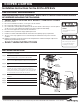
CEILING OR END MOUNT INSTALLATION
Step 1. De-energize the circuit at the junction box (J-box) where the exit sign is to be installed.
Step 2. Remove the exit sign stencil from the EXIT frame.
Step 3. Remove the canopy kit from inside the EXIT.
Step 4. Place the provided screws in the canopy screw holes. Tabs inside the holes will prevent the screws from falling out during installation.
Step 5. Remove the appropriate mounting hole plug on the top (ceiling mount) or side (end mount) of the frame.
Step 6. Place the canopy nose through the mounting hole until the side of the frame touches the canopy. Lock the frame onto the canopy by sliding the
f
rame in a direction parallel to the canopy length toward the narrow end of the mounting hole. Slide the frame until both snaps engage the canopy
nose preventing any motion back out of the hole.
Step 7. Feed the orange, black, and white wires through the canopy nose.
Step 8. Feed the wires from the J-box through the steel mounting plate, then attach the mounting plate to the J-box with installer provided hardware.
Step 9. Connect the J-box wires to the EXIT power supply wires using the wire nuts provided. Connect the white wire to neutral. If using 120V, connect
the black wire to the hot lead. If using 277V, connect the orange wire to the hot lead. Cap the unused lead. Press the wires into the J-box.
Step 10. Secure the EXIT canopy to the steel mounting plate using the screws placed in the canopy in step 4.
Step 11. For self powered units, attach battery leads to PCB.
Step 12. Snap the EXIT stencil onto the frame.
Step 13. Energize AC supply, LED display will come on.
SELF POWERED OPERATION: Depress the test switch. The LED display will remain lit and the charge LED will extinguish when the
switched to battery power. Release the test switch. The charge LED will illuminate and the LED display will operate from the AC supply.
MAINTENANCE: None required. For self powered units, replace the batteries as needed according to ambient conditions. However, we
recommend that the equipment be tested regularly in accordance with local codes.
NOTE: Servicing of any parts should be performed by qualified personnell. Only use replacement parts supplied by Cooper Lighting.
CAUTION: This equipment is furnished with a sophisticated low voltage battery dropout circuit to protect the battery from over discharge after its
useful output has been used. Allow 24 hours recharge time after installation or power failure for 90 minute testing.
TROUBLE SHOOTING GUIDE: If LED display or charge indicator LED does not illuminate, check the following:
1. Check AC supply – verify that unit has 24 hour AC supply.
2. Unit is shorted or battery is not connected.
3. Battery discharged. Permit unit to charge for 24 hours and then re-test.
4. If following the above trouble shooting hints does not solve your problem, contact your local Cooper Lighting representative for
assistance.
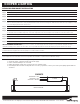
ORANGE LEAD - TO 277V
BLACK LEAD - TO 120V
WHITE LEAD - TO NEUTRAL
LED DISPLAY PC BOARD
POWER SUPPLY
PC BOARD
BATTERY
SCHEMATIC
Customer First Center 1121 Highway 74 South Peachtree City, GA 30269 770.486.4800 FAX 770.486.4801 1/3/11 049-205