Owners Manual, Monaco 6000A, 6000N, 6002A, 6002N MONACO 6000 OWNERS MANUAL Page 1 of 12 9700 B Owners Manual Monaco 6000.
Owners Manual, Monaco 6000A, 6000N, 6002A, 6002N Quality First – Customer First The Monaco 6000 is manufactured in the U.S. The product line is UL/ cUL listed and labeled. Lumiére stands behind the product with a three (3) year warranty and Cooper Lighting’s exclusive Customer First NationWide service network. Questions regarding these procedures may referred to: Lumiére Customer Service at (303) 393-1522. TABLE OF CONTENTS DESCRIPTION .....................................................................
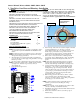
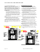
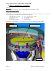
Owners Manual, Monaco 6000A, 6000N, 6002A, 6002N 1. Non Drive-Over Recessed Housing - Installation WARNING! NOTE: Four (4) screws will be visible on outer trim ring when TURN OFF POWER BEFORE INSTALLATION, MAINTENANCE, installation is complete. The orientation of screws is important, RELAMPING, OR SERVICING. orient housing as shown below.
Owners Manual, Monaco 6000A, 6000N, 6002A, 6002N 2. Drive-Over Recessed Housing - Installation WARNING! TURN OFF ALL POWER TO FIXTURE BEFORE INITIAL INSTALLATION, MAINTENANCE, RELAMPING, AND SERVICING. THIS FIXTURE IS DESIGNED FOR IN-GROUND INSTALLATION ONLY FOR USE AS AN UPLIGHT. DO NOT INSTALL IN CEILINGS OR IN VERTICAL SURFACES SUCH AS WALLS. SUITABLE FOR IN-GROUND DIRECT BURIAL, OR FOR INSTALLATION IN POURED CONCRETE, BRICK, OR OTHER NON-COMBUSTIBLE MASONRY MATERIALS ONLY.
Owners Manual, Monaco 6000A, 6000N, 6002A, 6002N 8) Lower the fixture housing into the hole. NOTE: Four (4) screws will be visible on outer trim ring when installation is complete. The orientation of screws is important, orient housing shown on pg 3. Trim ring screws will be located at 12 o’clock, 3 o’clock, 6 o’clock and 9 o’clock, relative to center of side-mounted wiring compartment. Wiring compartment should be perpendicular to the wall or illuminated surface.
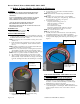
Owners Manual, Monaco 6000A, 6000N, 6002A, 6002N 3. Ballast & Lamp Module – Installation & Maintenance WARNING! TURN OFF ALL POWER TO FIXTURE BEFORE INITIAL INSTALLATION, MAINTENANCE, RELAMPING, AND SERVICING. DO NOT OVERTIGHTEN CAPTIVE SCREWS ON OUTER LENS! SET POWER DRIVERS TO LOWEST SETTING. THIS IS IMPORTANT TO AVOID PART DAMAGE.
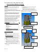
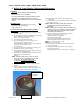
Owners Manual, Monaco 6000A, 6000N, 6002A, 6002N Slotted screw locks/unlocks orientation lamp adjustment Loosen this screw to remove sealing clamp Lamp module sealing clamp Figure 3 INSTALL TRIM RING/LENS ASSEMBLY 12) Install trim ring/lens assembly by aligning four threaded holes and attaching four socket head cap screws. RELAMPING PROCEDURE WARNING! TURN OFF ALL POWER TO FIXTURE BEFORE, RELAMPING, MAINTENANCE AND SERVICING.
Owners Manual, Monaco 6000A, 6000N, 6002A, 6002N 4. Guard, Louver, & Glare Shield - Installation Instructions WARNING! TURN OFF ALL POWER TO FIXTURE BEFORE INITIAL INSTALLATION, MAINTENANCE, RELAMPING, AND SERVICING. DO NOT OVERTIGHTEN CAPTIVE SCREWS ON OUTER LENS! SET POWER DRIVERS TO LOWEST SETTING. THIS IS IMPORTANT TO AVOID PART DAMAGE. THE MONACO 6000 AND 6002 FIXTURE IS DESIGNED FOR IN-GROUND INSTALLATION ONLY FOR USE AS AN UPLIGHT. DO NOT INSTALL IN CEILINGS OR IN VERTICAL SURFACES SUCH AS WALLS.
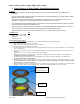
Owners Manual, Monaco 6000A, 6000N, 6002A, 6002N 5. Filters & Thermal Glass - Installation WARNING! 70 WATTS OR BELOW WITH TRL OPTION ARE RECOMMENDED FOR PEDESTRIAN AREAS INSTALLATION INSTRUCTIONS: Up to three accessories may be installed. The Internal Hex Cell Louver (LVR6), Temperature Reduction Lens (TRL), and Dichroic Filters are installed on top of Cast Bezel on inner module assembly.
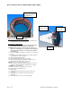
Owners Manual, Monaco 6000A, 6000N, 6002A, 6002N 6. Ballast & Lamp Module - Replacement Instructions WARNING! TURN OFF ALL POWER TO FIXTURE BEFORE REPLACING BALLAST ASSEMBLY. DO NOT OVERTIGHTEN CAPTIVE SCREWS ON THE TRIM RING! SET POWER DRIVERS TO LOWEST SETTING. THIS IS IMPORTANT TO AVOID DAMAGING PARTS.
Owners Manual, Monaco 6000A, 6000N, 6002A, 6002N Lamp angle adjust screw Slotted screw locks/unlocks orientation lamp adjustment Figure 2 Align notches in lamp module hanging frame over these pins Figure 3 LAMP ANGLE ADJUSTMENT – FOR MODELS 6000A AND 6002A ONLY. (FOR MODELS 6000N AND 6002N, GO TO STEP 12) 17) Adjust angle of lamp by inserting a hex wrench into the adjustment screw, as shown in Figure 2, and turning screw clockwise or counter-clockwise until lamp is at desired angle.
Owners Manual, Monaco 6000A, 6000N, 6002A, 6002N 7. Ballast Assembly – Replacement Instructions WARNING! TURN OFF ALL POWER TO FIXTURE BEFORE REPLACING THE BALLAST ASSEMBLY. DO NOT OVERTIGHTEN CAPTIVE SCREWS ON OUTER LENS! SET POWER DRIVERS TO LOWEST SETTING. THIS IS IMPORTANT TO AVOID PART DAMAGE. ORDER BALLAST WITH THE DESIRED WATTAGE AND VOLTAGE AS SPECIFIED ON BALLAST BOX LABEL. NOTE: USE THE SAME BOX TO SEND THE FAILED BALLAST BACK TO LUMIERE FOR FAILURE ANALYSIS.