
Specifications


Owners Manual, Monaco 6000A, 6000N, 6002A, 6002N
Page 12 of 12 9700 B Owners Manual Monaco 6000.doc
7. Ballast Assembly – Replacement Instructions
WARNING!
TURN OFF ALL POWER TO FIXTURE BEFORE
REPLACING THE BALLAST ASSEMBLY.
DO NOT OVERTIGHTEN CAPTIVE SCREWS ON OUTER
LENS! SET POWER DRIVERS TO LOWEST SETTING.
THIS IS IMPORTANT TO AVOID PART DAMAGE.
ORDER BALLAST WITH THE DESIRED WATTAGE AND
VOLTAGE AS SPECIFIED ON BALLAST BOX LABEL.
IN THIS PROCEDURE, YOU WILL REMOVE THE OLD
BALLAST AND ATTACH A REPLACEMENT.
MATERIAL LIST QTY
Ballast Replacement Assembly 1
Submersible Wire Nuts 6
Plastic Strain Relief 1
Return address label 1
BALLAST REPLACEMENT PROCEDURE
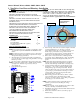
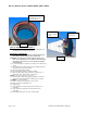
1) Loosen trim ring/lens assembly by loosening the four socket
head cap screws.
2) Pry trim ring/lens assembly off housing by inserting a flat
head screwdriver in side slots and turning.
3) Remove trim ring/lens assembly.
4) Lift sealed lamp assembly from housing.
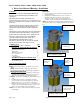
5) Disconnect ballast wires from incoming power by removing
wire nut connections in housing wiring box. (Discard wire
nuts. New water-tight water nuts, provided, must be used for
reconnection).
6) Disconnect ground wire from ballast to incoming power.
7) Disconnect ballast wire strain relief from the side of in-
ground housing.
8) Lift ballast assembly out of housing.
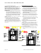
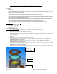
9) Cut plastic tie wrap attaching the green, blue, and white
wires coming out of the ballast box.
10) Cut through black mesh and wires that lead from ballast
assembly to lamp assembly, about 2” above the ballast box.
11) On lamp assembly, trim black mesh so that it is 1” shorter
than the wires inside it.
12) Strip green, blue, and white wires on lamp assembly to ½”.
13) Unpack new ballast kit. (plastic strain relief not shown)
NOTE: USE THE SAME BOX TO SEND THE FAILED
BALLAST BACK TO LUMIERE FOR FAILURE
ANALYSIS. ALL RETURNS MUST BE AUTHORIZED
BY YOUR FIELD SERVICE REPRESENTATIVE.
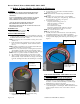
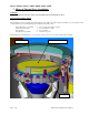
14) Insert mesh covered lamp wires downward through handle of
potted ballast assembly and slide plastic strain relief over
wires and mesh and tighten down on mesh and wire about 2
inches from end.
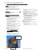
15) Connect the three SHORT color coded wires (green, blue,
and white) from the new ballast replacement assembly to
lamp assembly as follows: Twist stranded wires slightly
Insert wires together into new sealant wire nuts (provided)
Hold wires firmly and twist connector onto wires
NOTE: Do not twist wire nuts too hard
NOTE: Do not reuse wire nuts
16) Reconnect ballast to incoming power using new sealant wire
nuts (provided).
17) Reassemble fixture in the reverse order of disassembly.
Refer to Instruction Sheet #9704 – Ballast and Lamp Module
Installation Instructions.
18) Reattach trim ring/lens assembly by aligning four socket
head cap screws on trim ring with the four threaded holes on
housing, and tighten. DO NOT OVERTIGHTEN CAPTIVE
SCREWS ON OUTER LENS! SET POWER DRIVERS TO
LOWEST SETTING. THIS IS IMPORTANT TO AVOID
PART DAMAGE.
USE THREE SEALANT WIRE NUTS TO
CONNECT LAMP WIRES TO BALLAST
INSTALL
PLASTIC STRAIN
RELIEF BELOW
HANDLE.
ROUTE MESH
COVERED LAMP
WIRES DOWN
THROUGH
HANDLE