
Specifications

Owners Manual, Monaco 6000A, 6000N, 6002A, 6002N
Page 3 of 12 9700 B Owners Manual Monaco 6000.doc
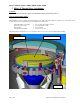
1. Non Drive-Over Recessed Housing - Installation
WARNING!
TURN OFF POWER BEFORE INSTALLATION, MAINTENANCE,
RELAMPING, OR SERVICING.
FIXTURE IS DESIGNED FOR IN-GROUND UP-LIGHT
INSTALLATION ONLY. DO NOT INSTALL IN CEILINGS OR
WALLS.
FIXTURE IS SUITABLE FOR IN-GRADE INTALL IN SOIL,
CONCRETE, BRICK, OR NON-COMBUSTIBLE MASONRY
MATERIALS ONLY.
FIXTURE MUST NOT COME INTO CONTACT WITH WOOD OR
OTHER COMBUSTIBLE MATERIALS OR SURFACES.
BARRICADE AND MARK OPEN HOLES, TRENCHES, OR
FIXTURES UNTIL INSTALLATION IS COMPLETE.
70 WATTS OR BELOW WITH TRL OPTION ARE
RECOMMENDED FOR PEDESTRIAN AREAS
FIXTURE MUST BE INSTALLED IN ACCORDANCE WITH
LOCAL & NATIONAL ELECTRICAL CODES.
MATERIAL LIST ` QTY
Recessed Housing, Monaco 6000/6002 1
The following materials supplied by others
½” Threaded Rod, 36” Sections 3
½”-13 Nut 3
2” Fender Washer 3
Free drain material (CBR of 20 or greater) . 6 yards
¾” NPT Connector 1
INSTALLATION PROCEDURE
Models 6000A, 6000N, 6002A & 6002N
NOTE: These instructions are for non drive-over application. Drive-
over application require kit # 6000-DSB and Installation Sheet
#9702.
NOTE: Soil must be prepared as specified by civil or soils engineer.
NOTE: Compact trenches to 90% relative compaction and comply
with pavement design specifications.
1) Select threaded ports in side-mounted wiring compartment for
power in. Knock out selected plugs, being careful not to damage
threads in port walls.
2) Dig a hole at least 18 inch diameter at base and 38 inches deep.
NOTE: ½” threaded rod will be used to stabilize housing. Cut three
(3) lengths of ½” threaded rod (provided by others) to
approximately 36”.
3) Lower fixture housing into hole.
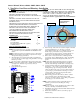
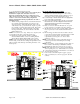
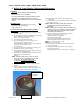
NOTE: Four (4) screws will be visible on outer trim ring when
installation is complete. The orientation of screws is important,
orient housing as shown below. Trim ring screws will be located
at 12 o’clock, 3 o’clock, 6 o’clock and 9 o’clock, relative to
center of side-mounted wiring compartment. Wiring
compartment should be perpendicular to the wall or illuminated
surface.
THREADED HOLES
FOR TRIM RING
SCREWS, 4X
WALL
90°
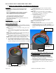
4) With housing oriented in hole, locate three lengths of threaded
rod in integral flange slots on outer edge of housing.
Temporarily thread two nuts to top of threaded rod to protect
threads. Tap top of threaded rods to get them started in
ground. Remove housing from hole. Continue driving rods
straight into ground until 6 inches below ground level.
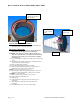
5) Fill bottom of hole with 18 inches of drainage material
(provided by others). Material must be “select” free draining
material with a California Bearing Ratio (CBR) of 20, or
greater.
NOTE: Water will collect and drain through bottom of fixture
housing. Verify drainage through fixture bottom will not
adversely affect hardscape around fixture or hardscape base.
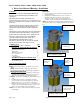
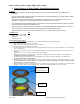
6) Lower the fixture housing into hole with threaded rods in
integral slots. Add or remove drainage material beneath
housing until top edge of housing is level with finished
surface. Install concrete pour cover (if provided) securely on
top of housing to prevent debris from entering. Level and
secure housing to threaded rods using nuts and washers
(provided by others). See figure.
7) Run incoming power lines and connect conduit to selected
ports in mounted wiring compartment using ¾” NPT
connectors (provided by others). Access wiring compartment
by twisting top cover counter-clockwise.
NOTE: Conduit connections must be sealed with waterproof
material to prevent water from leaking into wiring
compartment.
NOTE: Leave at least 6” of wire extending from conduit, for later
connection with lamp module/ballast assembly.
8) Back-fill hole and compress material. Finish surface material
so that it is even with top.
9) Finish surface material so that it is even with top edge of
fixture housing.