
Specifications

Owners Manual, Monaco 6000A, 6000N, 6002A, 6002N
Page 4 of 12 9700 B Owners Manual Monaco 6000.doc
2. Drive-Over Recessed Housing - Installation
WARNING!
TURN OFF ALL POWER TO FIXTURE BEFORE INITIAL
INSTALLATION, MAINTENANCE, RELAMPING, AND
SERVICING.
THIS FIXTURE IS DESIGNED FOR IN-GROUND
INSTALLATION ONLY FOR USE AS AN UPLIGHT. DO NOT
INSTALL IN CEILINGS OR IN VERTICAL SURFACES SUCH
AS WALLS.
SUITABLE FOR IN-GROUND DIRECT BURIAL, OR FOR
INSTALLATION IN POURED CONCRETE, BRICK, OR
OTHER NON-COMBUSTIBLE MASONRY MATERIALS
ONLY.
FIXTURE MUST NOT COME INTO CONTACT WITH WOOD
OR OTHER COMBUSTIBLE MATERIALS OR SURFACES.
BARRICADE AND MARK OPEN HOLES, TRENCHES, OR
FIXTURES UNTIL INSTALLATION IS COMPLETE.
70 WATTS OR BELOW WITH TRL OPTION ARE
RECOMMENDED FOR PEDESTRIAN AREAS
FIXTURE TO BE INSTALLED IN ACCORDANCE WITH
LOCAL AND NATIONAL ELECTRICAL CODES.
MATERIAL LIST QTY
Recessed Housing, Monaco 6000/6002 1
Drive-Over Kit # 6000-DSB (Must Be Ordered)
Drive-Over Brackets 4
Threaded Rod, 2 ft Sections 6
Anchor Bolts ` 6
Threaded Rod Couplers 3
½”-13 x 1” Bolts 4
½”-13 Nuts 29
2” Fender Washer 3
Other Material Required-Provided by others
Free drain material (CBR of 20 or greater), approx.0.6 yard
One ¾” NPT Connector 1
INSTALLATION PROCEDURE
MONACO 6000 AND 6002
NOTE: Soil must be prepared as specified by a civil or soils
engineer.
NOTE: Trenches should be compacted to 90% relative
compaction and comply with pavement design specifications.
RECESSED HOUSING PREP
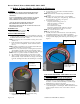
1) Determine which of the four (4) threaded ports in the side-
mounted wiring compartment will be used to run power to
the fixture. Knock out the plug in the required ports.
CAUTION: Be careful not to damage the threads inside the port
walls.
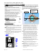
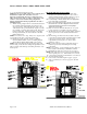
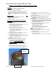
2) Assemble the four (4) drive-over brackets around the
recessed housing, as shown in the diagram. Connect the
brackets with ½”-13 x 1” bolts and ½”-13 nuts (Qty 8).
3) Attach six (6) anchor bolts, ½-13 x 8” x 3” to the drive over
brackets as shown in the diagram. Attach ½-13 nuts to the
anchor bolts approximately 1” above the bracket.
NOTE: The “L” section of the bolt must be facing out as shown
in the diagram.
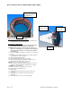
HOLE PREP
4) Dig a hole that is at least 18 inches in diameter at the base
and 38 inches deep.
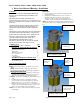
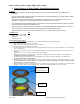
5) Included in the installation kit are six 2 foot sections of
threaded rod and three couplers. Join two sections of
threaded rod with a coupler to make a 4 ft threaded rod
assembly. Do the same with the other threaded rod sections.
NOTE: The threaded rod assemblies will be pounded into the soil
and attached to the housing to stabilize the fixture for the cement
pour.
Drive-over brackets
Qty - 4
½ x 13 x 1” bolts-qty 8
½ x 13 nuts-Qty 8
Drive-over Bracket Assembl
y
½-13 nut on
top and
bottom of
bracket
2” fender
washer and
½-13 nut
Anchor bolts and
nuts – qty 6,
L must face out
Threaded rod-join
two sections, with
coupler, to make
one 4 ft section
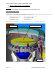
Complete Recessed Housing as
it will appear in the ground