
Specifications
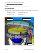

Owners Manual, Monaco 6000A, 6000N, 6002A, 6002N
3. Ballast & Lamp Module – Installation & Maintenance
WARNING!
TURN OFF ALL POWER TO FIXTURE BEFORE INITIAL
INSTALLATION, MAINTENANCE, RELAMPING, AND
SERVICING.
DO NOT OVERTIGHTEN CAPTIVE SCREWS ON OUTER
LENS! SET POWER DRIVERS TO LOWEST SETTING.
THIS IS IMPORTANT TO AVOID PART DAMAGE.
70 WATT OR BELOW WITH TRL OPTION ARE
RECOMMENDED FOR PEDESTRIAN AREAS
FIXTURE TO BE INSTALLED IN ACCORDANCE W/ LOCAL
AND NATIONAL CODES
MATERIAL LIST QTY
Ballast and Lamp Module Assembly 1
Submersible Wire Nuts (included) 3
INSTALLATION PROCEDURE
NOTE: Housing assembly must be properly installed in ground prior
to ballast and lamp module installation. Refer to Recessed Housing
Installation Sheet # 9701, 9702, or 9703.
NOTE: If a concrete pour cover is attached to housing, remove and
discard cover.
1) If side mounted wiring compartment on housing is accessible,
remove cover from compartment. (Twist counter-clockwise to
remove.)
NOTE: If wiring compartment is not accessible, fixture will need to
be wired from inside of recessed housing.
NOTE: Remove any debris in bottom of housing that may interfere
with installation of ballast assembly and sealed lamp module.
2) Place ballast assembly in bottom of housing with wires facing up.
NOTE: There is no specific orientation for ballast assembly.
3) Set sealed lamp module assembly on ground next to housing.
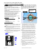
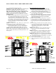
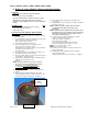
4) There is a plastic strain relief attached to free wires coming off
ballast assembly. Attach strain relief to housing by removing nut
from stud, attaching strain relief, and reattaching nut. See Figure
1.
5) Route wires through opening in side mounted wiring
compartment or out of top of housing.
6) Connect three color coded wires from ballast assembly to
incoming power wires.
NOTE: Wires must be connected using submersible wire nuts
provided.
NOTE: There are two green ground wires, one from Ballast
Assembly and one that goes to Lamp Housing. Both must be
wire nut attached to incoming power ground.
7) Connect wires as follows:
Strip wires from incoming power to ½”.
Align frayed strands or conductors.
Do not pre-twist wires.
Twist stranded wires slightly.
Insert wires together through sealant into connector.
Hold wires firmly and twist connector onto wires.
NOTE: Do not twist wire nuts too hard.
NOTE: Do not reuse wire nuts.
8) Carefully insert wires with wire nuts into side mounted wiring
compartment. Replace top cover on wiring compartment.
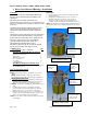
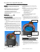
9) Carefully place lamp module into housing. Align the two notches
in lamp assembly hanging frame with two pins in housing. See
Figure 2.
LAMP ANGLE ADJUSTMENT – FOR MODELS 6000A AND
6002A ONLY.
(FOR MODELS 6000N AND 6002N, GO TO STEP 12)
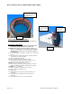
10) Adjust angle of lamp by inserting a hex wrench into the
adjustment screw, as shown in Figure 2, and turning screw
clockwise or counter-clockwise until lamp is at desired angle.
Maximum tilt is 15 degrees from vertical.
Lamp angle adjust
screw
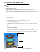
11) After desired angle has been reached, the light direct may be
rotated 360 degrees to orient the light. When orientation has been
achieved, tighten slotted set screw on lens collar as shown in
Figure 3.
Attach strain relief
from ballast
assembly here
Align notches in lamp
module hanging frame
over these pins
Figure 2
Figure 1
Page 6 of 12 9700 B Owners Manual Monaco 6000.doc