
Specifications

Owners Manual, Monaco 6000A, 6000N, 6002A, 6002N
4. Guard, Louver, & Glare Shield - Installation Instructions
WARNING!
TURN OFF ALL POWER TO FIXTURE BEFORE INITIAL INSTALLATION, MAINTENANCE, RELAMPING, AND
SERVICING.
DO NOT OVERTIGHTEN CAPTIVE SCREWS ON OUTER LENS! SET POWER DRIVERS TO LOWEST SETTING. THIS IS
IMPORTANT TO AVOID PART DAMAGE.
THE MONACO 6000 AND 6002 FIXTURE IS DESIGNED FOR IN-GROUND INSTALLATION ONLY FOR USE AS AN
UPLIGHT. DO NOT INSTALL IN CEILINGS OR IN VERTICAL SURFACES SUCH AS WALLS.
SUITABLE FOR IN-GROUND DIRECT BURIAL, OR FOR INSTALLATION IN POURED CONCRETE, BRICK, OR OTHER
NON-COMBUSTIBLE MASONRY MATERIALS ONLY.
FIXTURE MUST NOT COME INTO CONTACT WITH WOOD OR OTHER COMBUSTIBLE MATERIALS OR SURFACES.
70 WATTS OR BELOW WITH TRL OPTION ARE RECOMMENDED FOR PEDESTRIAN AREAS
FIXTURE TO BE INSTALLED IN ACCORDANCE WITH LOCAL AND NATIONAL ELECTRICAL CODES.
MATERIAL LIST QTY
Installed Monaco 6000 or 6002 1
Guard, Louver, or Glare Shield 1
Clamp Ring 1
Long Captive Screws 4
INSTALLATION INSTRUCTIONS
1. Do not remove Clamp Ring from Guard, Louver, or Glare Shield because these are matched pairs.
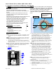
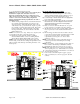
2. Remove Outer Lens Assembly from top of fixture.
3. Remove four short captive screws from Outer Lens Assembly.
4. Reposition Outer Lens Assembly on top of fixture.
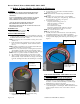
5. Look through trim ring holes and assure that they are aligned with holes in nut plate. (Note: This alignment is very critical with
accessory installation)
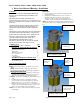
6. Place Accessory Assembly (Accessory with Clamp Ring Installed) on top of trim ring and align accessory to provide desired
shielding.
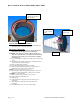
7. Align holes of accessory assembly with holes in Outer Lens Assembly.
8. Thread one long captive screw through accessory assembly, through trim ring, and into the nut plate. “DO NOT FULLY
TIGHTEN THE SCREW AT THIS POINT”
9. Thread remaining screws through accessory, through Outer Lens Assembly, and into the Nut Plate. “DO NOT FULLY
TIGHTEN THE SCREWS AT THIS POINT”.
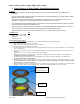
10. After last screw is loosely installed, realign accessory to provide desired shield orientation. Gradually tighten the four screws. DO
NOT OVERTIGHTEN CAPTIVE SCREWS ON OUTER LENS! SET POWER DRIVERS TO LOWEST SETTING. THIS IS
IMPORTANT TO AVOID PART DAMAGE.
11. When re-lamping, removal of one of the captive screws may make it easier to align the Accessory/Outer Lens Assembly with the
Nut Plate. You may then loosen the remaining screws and remove trim ring with the Guard, Louver, or Shield.
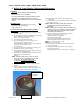
Outer Lens
Assembl
y
Nut Plate
Accessory Assembly
(Accessory with
Clamp Ring Installed)
Page 8 of 12 9700 B Owners Manual Monaco 6000.doc