WaveLinx User and Programming Manual This document is intended for installers, set-up technicians and IT professionals of the WaveLinx Wireless Connected Lighting System ATTENTION Engage appropriate network security professionals to ensure all lighting control system hardware and servers are secure for access. Ensure IT professionals review the WaveLinx network architecture document found at the end of this manual. Network security is an important issue.
WaveLinx User Manual WaveLinx User Manual - Table of contents Becoming Familiar with WaveLinx System Components.....................................................................................................................5 Bringing the System Online.................................................................................................................................................................9 Step 1: Confirming Device Installation...................................................
WaveLinx User Manual Adding Schedule Events to the Control Strategy......................................................................................................................91 Basic Schedule Event Screen Information..................................................................................................................95 Modifying and Testing Demand Response Behavior.................................................................................................................
WaveLinx User Manual Welcome and Introduction The WaveLinx Wireless Connected Lighting System offers wireless, code-compliant control in a simple, easy to install and manage format. Designed with ease of use in mind, the WaveLinx wireless system installs and configures quickly to capture immediate energy and cost savings.
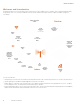
WaveLinx User Manual Becoming Familiar with WaveLinx System Components The following devices may be used in a WaveLinx Wireless Connected Lighting System. Insight Manager Pro Insight Manager Enterprise and Virtual Lighting Xpert Insight The Insight Manager and Lighting Xpert Insight software are optional for sites that want to have enterprise-level functionality.
WaveLinx User Manual WaveLinx Dimming Switchpack with 0-10V WSP-MV-010 Use the WaveLinx Dimming Switchpack with 0-10V to wirelessly control a zone of switched loads or 0-10V lighting loads. Each switchpack operates as a WaveLinx wireless router and endpoint. The switchpack is rated for control of LED or other electronic ballast loads of up to 16 amps and general purpose or receptacle loads of up to 20 amps.
WaveLinx User Manual WaveLinx Outdoor Integrated Sensor The WaveLinx Outdoor Integrated Sensor installs as an option into many Eaton outdoor light fixtures. The fixture mounted sensor operates as a WaveLinx wireless communications router as well as an occupancy sensor, closed loop daylight sensor, and power measurement point. Different models allow for low mounting heights of 7-15 feet (2.1 – 4.5m) or high mounting heights of 15-40 feet (4.5 – 12.2m).
WaveLinx User Manual WaveLinx Wallstation (standard line voltage powered) WaveLinx Battery Powered Wallstation Use the WaveLinx Wallstations to manually operate wirelessly connected loads. Models include standard WaveLinx Wallstations that connected to line voltage power and WaveLinx Battery Powered Stations that simplify retrofit installations. Operation includes button configuration support for scene selection, scene raise/lower, zone level, zone raise/lower, and scene and zone toggle capability.
WaveLinx User Manual Bringing the System Online The WaveLinx Wireless Connected Lighting System configures quickly to allow immediate energy savings.
WaveLinx User Manual WaveLinx Outdoor Integrated Sensor LED in sensor window should blink green with motion detection. The green LED color indicates that the integrated sensor has not yet been paired with a Wireless Area Controller. (If the LED blinks white, this indicates that the sensor has been previously paired with a Wireless Area Controller. See page 135 for information on resetting the pairing.) WaveLinx Tilemount Sensor Fixture operates via the onboard daylight and occupancy sensors.
WaveLinx User Manual WaveLinx Wallstation Battery Powered All LEDs will be off as the station is automatically in “sleep” mode to conserve battery life. A red LED below the bottom button may flash if a finger is within 5 cm of the buttons or a button is pressed, triggering the proximity sensor to “wake” the station and request an updated LED status. The button LEDs should remain off until the station is paired with the WAC.
WaveLinx User Manual 3: Press and release (1 second press) the PAIR button located on the rear panel of the Wireless Area Controller. The blue 802.15.4 LED on the Wireless Area Controller will blink at a rate of one blink per second to indicate the Wireless Area Controller is in pairing mode. The Wireless Area Controller pairing mode automatically times-out after 60 minutes or can be manually exited by pressing and releasing (1 second press) the PAIR button again. 12 www.eaton.
WaveLinx User Manual 4: Place devices into pairing mode. See the below chart for information on how to place specific devices in pairing mode: Device Type How to place pairing mode WaveLinx Wireless Dimming Switchpack (WSP-MV-010: 120-277VAC model) Cycle the power (switch OFF and then ON) of each identified circuit using the circuit breakers. This places the devices into pairing mode and starts their search for a Wireless Area Controller.
WaveLinx User Manual WaveLinx Wallstation Press any button on the Wallstation to initiate a PAIR request from any unpaired wallstation. •• On the standard WaveLinx Wallstation (line voltage powered), the LED on the button pressed should flash slowly for approximately 10 seconds. •• On the WaveLinx Battery Powered Wallstation, the red LED below the buttons may flash briefly when the proximity sensor detects someone near and may flash intermittently during the pairing process.
WaveLinx User Manual Device Successfully Paired Behavior (during initial pairing) WaveLinx Wireless Dimming Switchpack (WSP-MV-010: 120-277VAC model) Connected 0-10V dimmable fixtures dim to 10%. WaveLinx Wireless Dimming Switchpack (WSP-CA-010: 120-347VAC model) Fixture dims briefly when paired then turns ON to a brighter light level and remains ON. It may be difficult to review paired behavior during the initial pairing cycle.
WaveLinx User Manual WaveLinx Tilemounted Sensor Paired device behavior: Connected 0-10V dimmable fixtures dim to 10%. LED in sensor window should blink WHITE with motion detection. WaveLinx Ceiling Sensor Not applicable for this device. WaveLinx Wireless Outdoor Lighting Control Module Paired device behavior: Fixture dims to 10%. Not applicable for this device.
WaveLinx User Manual During the pairing process, as devices join, a message may be briefly displayed on the screen. The mobile application will also display a device count of how many devices are paired with the Wireless Area Controller. Pairing Device count Device joined message Tap on the device count to open a link that shows a paired device list organized by device type. Scroll down to view more items within this window.
WaveLinx User Manual Quick Links for Common Questions •• Pairing mode timed out before I was done adding my battery powered ceiling sensors or before I confirmed my devices paired properly. What should I do? See the answer on page 133. •• One or more of my devices did not pair. What should I do? See the answer on page 133. •• I have more than one Wireless Area Controller in my facility. A device or multiple devices paired with the wrong controller. How do I resolve this? See the answer on page 133.
WaveLinx User Manual 3: Ensure that Wi-Fi has been turned ON in the smartphone or tablet, and then navigate to the list of available Wi-Fi networks. Locate the Wi-Fi network with the name Eaton-XXXXXXXXXXXX (where X is a string of letters and numbers). If there are multiple Wireless Area Controllers at the facility, more than one wireless network with this naming criteria may appear. Select the Wi-Fi network EatonXXXXXXXXXXXXXX where the X characters match the MAC ID noted in the previous step.
WaveLinx User Manual 5: In the log in screen, enter the username and password for the administrator user (these are case sensitive). •• Default Username: WclAdmin •• Default Password: wclAdmin Select the option to save credentials to remember the login credentials automatically on this device for future connections and then select the log in button. After a brief refresh period, the areas list will be displayed indicating a successful connection.
WaveLinx User Manual Mobile Application Basic Familiarity Before proceeding to the next step, become familiar with the basics of the WaveLinx Mobile Application. This section describes the terminology, icons, and basic navigation used in the mobile application. Areas Construction grouping automatically places all paired devices into a default construction area. Default area Each Wireless Area Controller allows the creation of up to 15 areas plus the default construction area.
WaveLinx User Manual Zones In any area, controlled loads are organized into zones. A zone is a “group” of one or more lights, receptacles or other loads that are to be controlled together in the exact same way. The WaveLinx Mobile Application creates three zones by default. Zone 1 and 2 are automatically created for dimmable lighting devices. Zone 3 is automatically created for switched receptacle devices. Up to 16 total zones may be used in each area to meet application needs.
WaveLinx User Manual Devices In the mobile application, each device type has a distinctive icon for quick identification.
WaveLinx User Manual Icon colors indicate different device conditions. Icon Color Device Condition Device Green •• The device is communicating and operational Device Gray or Red •• The device is no longer communicating to the mobile application. •• Upon reboot devices that do not communicate with the Wireless Area Controller after the reboot completes will remain gray.
WaveLinx User Manual For further information, tap any zone to see the devices that are assigned to the zone. Tap the desired zone View the controlled devices Devices that do not directly wire to a specific load (lighting or receptacles) such as wallstations and ceiling sensors will display in the in area section in the middle of the display screen. Assigned wallstations and ceiling sensors will appear here www.eaton.
WaveLinx User Manual Other icons There are many icons used to perform functions in the mobile application. Icon Functionality Displays menu options. Refreshes the current screen. OR From the main menu, discovers new devices. Indicates that the Wireless Area Controller is in pairing mode. Restarts the Wireless Area Controller (reboot). Displays paired devices. Adds an item to the displayed list. Deletes the item. Opens an editor for the item.
WaveLinx User Manual Step 4: Organizing Devices into Controlled Areas and Zones Once the communication between the WaveLinx Mobile Application and the Wireless Area Controller is established, the organization of the system begins. In this section, the mobile application will be used to identify and group devices into unique areas and zones for automatic code commissioning operation. 1: Go to the location in the facility that will be programmed first.
WaveLinx User Manual 3: (Optional) If the area needs additional zones beyond the provided defaults (dimmable lighting zones 1 and 2, and receptacle zone 3), tap the plus sign icon in the zones section to add a new zone. Type a descriptive name for the zone, and then select the zone type (dimmable, receptacle, or non-dimmable switched) other parameters may be left at defaults or modified for the application. Save the settings to advance into the new zone’s screen.
WaveLinx User Manual 4: Next assign the controlled load devices to the proper zones. While still in the area screen for the desired space, place the first controlled load device in the room into identification mode as described in this section. Once the device is identified, drag and drop the device into the desired zone. Repeat this step for additional controlled loads until all loads in the area are assigned. Touch and drag the identified endpoint into the desired zone www.eaton.
WaveLinx User Manual How to initiate identification mode in controlled load devices: Device Identification Mode WaveLinx Integrated Sensor and WaveLinx Tilemount Sensor For fixtures mounted at reasonable mounting heights, use a laser pointer or bright, focused beam flashlight to trigger identification mode. Standing beneath the sensor, shine the light directly into the sensor lens for 3-4 seconds. The timing needs to be precise for the identification mode to respond.
WaveLinx User Manual WaveLinx Industrial Integrated Sensor - High bay mounting Use the mobile application blink to identify feature to identify these types of devices. Each of these devices has an icon that identifies the device type. Locate the first icon that matches the desired device type In the all unassigned devices section. Double tap the icon to place it in blink to identify mode. The icon will appear to pulse and a load matching that type should respond.
WaveLinx User Manual 5: Next assign any wallstations and ceiling sensors to the area. While still in the area screen for the desired space, place the first device in the room into identification mode as described in this section. Once the device is identified, drag and drop the identified device into the in area device section of the screen. Repeat this step until all wallstations and ceiling sensors in the room are identified and assigned.
WaveLinx User Manual 6: Once all devices are assigned, tap on the paired device count showing at the top of the area screen. Verify that the device types and counts match the actual quantity of devices that should be in that space. 7: (Read important note below before proceeding). Repeat the procedures in this section for additional areas controlled by the Wireless Area Controller. Once devices are assigned, areas will begin operation with the automatic code commissioning programming.
WaveLinx User Manual Quick Links for Common Questions •• I am done assigning my devices to areas but I still have devices showing in my unassigned device list. What should I do? See the answer on page 137. •• During configuration, I found a device that was not powered. How do I get the device it to appear in the mobile application so that I can assign it? See the answer on page 137. •• There is a device in the space that is not showing in the mobile application.
WaveLinx User Manual Using the WaveLinx Mobile Application for Personal Control The WaveLinx Mobile Application allows occupants to have personal control of the lighting in their area. Use this section to: •• Connect to the Wireless Area Controller as a personal control user. •• Assign a favorite area to open automatically for each personal control user. •• Control the lighting as a personal control user.
WaveLinx User Manual Assign a Favorite Area for Personal Control Users It is possible to set each user’s mobile device to open the WaveLinx Mobile Application to a favorite area by default for quick and easy access to lighting and receptacle loads in their location. Note that this is stored on the device and not linked to the mobile account. Any user logged in to the same mobile device will share this favorite’s area.
WaveLinx User Manual Control the Lighting as a Personal Control User The mobile application’s personal control feature allows the occupant of the space to control lighting in their location within defined programmed parameters. Occupancy/vacancy sensing, daylighting, and demand response settings will define the range within which the occupant can: •• Raise and lower the light level of all controlled zones in the area. •• Adjust the light level of individual dimmable zones in the area.
WaveLinx User Manual To issue pre-programmed scenes, use the controls in the scene menu. Tap to open scene selection screen Tap on desired scene to activate pre-programmed scene levels Quick Links for Common Questions •• When I log in as the personal control user, not all of the scenes are showing. Why is this happening? See the answer on page 137. •• In personal control, I selected a scene but the lighting did not appear to change. Why? See the answer on page 138.
WaveLinx User Manual Modifying Names of Areas, Zones and Devices Generic names will be assigned to the default zones and to devices during the configuration process. It is possible, but not required, to change the default names of areas, zones and devices at any time using the edit feature. To modify the name of an area, zone or device: Step 1: Open the WaveLinx Mobile Application and establish a connection with the Wireless Area Controller as the administrator user.
WaveLinx User Manual Modifying Scene Response The WaveLinx system allows for sixteen programmable scenes per area. These scenes are labeled scene 0 through scene 15. Each scene is pre-programmed for a light level or ON/OFF response to allow for functionality from occupancy sensors and wallstations once devices have been PAIRED in the construction group or assigned to an area.
WaveLinx User Manual Step 3: At the top-right of the area screen, tap the scene menu to display the area’s scenes. Select the scene menu to open the area’s scenes Step 4: In the area’s scene list, locate the row for the desired scene. Tap the arrow that is at the far-right in the desired row to open the scene for modification. Touch arrow to access scene modification screens www.eaton.
WaveLinx User Manual Step 5: Once in the screen, modify the scene with the desired options: •• Select whether the adjustment will be “live” to see changes in real-time or “static” if light levels should not change during the modification. •• Use the adjustment tools within each zone to modify the scene response, adjusting the percentage for dimmable zones or ON/OFF for switching zones. If there are more than two zones in the area, swipe left and right to navigate to additional zones.
WaveLinx User Manual Modifying Zone Response Zone response may be modified by changing the default maximum and minimum levels (high and low end trims) and by modifying the operational mode default First ON/Last OFF behavior. Modifying Minimum and Maximum Levels (High and Low End Trims) The mobile application’s minimum and maximum level settings combined with the fixture’s native driver or ballast range determines the total dimming capability of the luminaire.
WaveLinx User Manual Step 3: In the area screen, select the desired zone. Select zone to modify Step 4: In the zone screen, select the pencil icon in the upper-right corner to open the edit function. Select the pencil icon to edit the zone 44 www.eaton.
WaveLinx User Manual Step 5: Use the minimum level and maximum level adjustments to select the desired trim values. Touch the save button to save the change. Adjust the minimum and maximum levels Save the settings NNote: It is possible to assign a dimmable fixture to a non-dimmable zone to allow it to act like a switched load. In this instance, a maximum level may be set to set a high end trim.
WaveLinx User Manual Step 3: In the area screen, select the desired zone. Select zone to modify Step 4: In the zone screen, select the pencil icon in the upper-right corner to open the edit function. Select the pencil icon to edit the zone Step 5: Use the drop down selection to choose the operation mode and settings. See the details below regarding the available options and resulting behavior. 46 www.eaton.
WaveLinx User Manual Use the operation mode drop down Save the settings Select the desired operation mode Zone Operational Mode Parameter Details: •• First On/Last Off: If the zone is OFF, switched loads in the zone will respond ON when any command level other than 0% is received. If the zone is ON, switched loads within the zone will turn OFF when the zone reaches a 0% (OFF) light level.
WaveLinx User Manual Modifying Wallstation Button Response Once assigned to their controlled area, WaveLinx Wallstations operate with default functionality. The following charts describe the default wallstation button response for the standard WaveLinx Wallstations (line voltage powered) and for the battery powered WaveLinx Wallstations.
WaveLinx User Manual Battery Powered Wallstation Default Button Response Scene 1 Scene 1 Scene 1 Scene 1 Scene 1 Scene 1 Full Lights Full Lights Full Lights Off Off Off Scene 2 Scene 2 Scene 2 Off Off Off Scene 1 Scene 1 Scene 2 Scene 2 Off Off WB2L-x Button #1: Scene 1 Button #2: Scene 0 Scene 1 Half Lights Half Lights Half Lights Scene 2 Raise Raise Raise Full Lights Full Lights Full Lights Off Lower Lower Lower Off Off Off WB2L-S1-W WB2L-S1-W WB2L-S1-W WB2L-
WaveLinx User Manual Changing Default Button Response Each wallstation button’s default responses may be modified to customize operation. To change the response of a wallstation button: Step 1: Open the WaveLinx Mobile Application and establish a connection with the Wireless Area Controller as the administrator user. Step 2: In the areas list, select the area that contains the wallstation to be modified. Step 3: In the area screen, tap the icon for the desired wallstation to open it for editing.
WaveLinx User Manual Step 4: In the wallstation screen, ensure that the faceplate configuration shown matches the faceplate of the wallstation model being configured. For standard line voltage powered wallstations only, if necessary, select the correct configuration from the drop down list. (Battery powered wallstations will not have the option to change the faceplate configuration.) Optionally, use the pencil icon edit feature to rename the wallstation.
WaveLinx User Manual Step 6: Repeat steps 4 and 5 for additional buttons on the selected wallstation. Repeat this procedure for additional wallstations in the space or use the copy function described in the next section. Wallstation Parameter Definitions: •• No action: The button will not perform any command if pressed. •• Select scene: The button will issue the selected scene to the selected area using either the default area fade rate, or a uniquely defined fade rate.
WaveLinx User Manual Copying Wallstation Programming to Other Wallstations In many applications, wallstations within the same room may perform the same functions. In addition, wallstations in other rooms may have the same behavior. The mobile application makes it easy to copy customized wallstation programming to other wallstations. In order to copy wallstation programming, the wallstations must be the same type and have the same faceplate configuration, i.e.
WaveLinx User Manual Step 4: In the wallstation screen, select the pencil icon to open the edit feature. Tap in the name field and type a unique name for this wallstation that will be easily recognized. Touch the save button to save the change and then tap the back button to return to the area list.
WaveLinx User Manual Step 6: In the edit screen, tap the drop down in the copy section and select the name of the programmed wallstation. If desired, type a name for the new wallstation and then tap save. If desired, give this wallstation a descriptive name Tap drop down Tap to save Select the previously configured wallstation Once the wallstation is saved, a message may appear briefly stating that the copy was successful.
WaveLinx User Manual Additional Wallstation Information There are some helpful items available in the mobile application to assist with wallstation identification and battery monitoring. •• Blink to Identify In an area that has a large quantity of the same model of standard line voltage powered wallstations, use the mobile application’s blink to identify feather to identify which wallstation is which.
WaveLinx User Manual Modifying Occupancy Sensor Response The WaveLinx Mobile Application allows modification of some occupancy sensor functions at the individual sensor level and other functions at a grouped level called an occupancy set. An occupancy set is a group of occupancy sensors that operate together to control the space. When an area is created, any occupancy sensor assigned to the area is automatically grouped into a default occupancy set to control the loads in the area.
WaveLinx User Manual Step 3: In the area screen, select the gear icon in the upper-right corner to open the area menu and then select the occupancy set option. Select the gear icon to open the area menu Select the occupancy sets option Step 4: Next, select the desired occupancy set to modify. Occupancy set 1 will be there by default. Tap on the occupancy set to open the configuration screen 58 www.eaton.
WaveLinx User Manual Step 5: In the attributes screen, modify the desired settings. Note that this screen also indicates if any sensor in the occupancy set is currently detecting motion. View real-time status of the sensor • Dark white icon-occupied • Light white icon - vacant Attribute screen Define occupancy set functionality per the provided chart Setting Default Description Mode Occupancy Select the option of occupancy or vacancy mode.
WaveLinx User Manual Step 6: Next, view the zone and sensors screens to review the devices that are affected by this occupancy set or to make a changes to the controlled zones or assigned sensors. •• Remove or add controlled zones by dragging and dropping the zone icon between the controlled zones list and the area zones lists. Zones in the controlled zones list will be operated by the occupancy set. The default zones should automatically appear in this section.
WaveLinx User Manual Viewing and Adjusting Individual Sensor Settings Specific settings are adjusted at the sensor level including adjusting sensitivity, enabling and disabling the occupancy functions of a sensor, and enabling and disabling the occupancy sensor’s LED. It is also possible to view the occupancy set the sensor belongs to, the programmed hold time, the current sensor status, the battery level for battery powered ceiling sensors.
WaveLinx User Manual Step 4: Modify or view the desired settings within the sensor screen. View real-time status of the sensor: • Dark blue icon-occupied • Light blue icon - vacant View currently assigned occupancy set hold time Modify sensor setting per the provided chart View currently assigned occupancy set Integrated sensor only: • Activate blink to identify to locate the fixture connected to this sensor.
WaveLinx User Manual To create a new occupancy set: Step 1: Open the WaveLinx Mobile Application and establish a connection with the Wireless Area Controller as the administrator user. Step 2: In the areas list, select the area that requires the additional occupancy sets. Step 3: In the area screen, select the gear icon in the upper-right corner to open the area menu and then select the occupancy set option. Select the gear icon to open the area menu Select the occupancy sets option www.eaton.
WaveLinx User Manual Step 4: Select the plus sign icon to create an additional occupancy set, and then select one of the occupancy sets to begin configuration. Tap the plus sign icon to add another occupancy set. Tap on one of the occupancy sets to modify the configuration Step 5: Optionally rename the occupancy set by tapping the pencil icon. Then define the behavior for the occupancy set. Tap the pencil icon to edit the occupancy set name Define the desired behavior. 64 www.eaton.
WaveLinx User Manual Step 6: While still in the occupancy set screen, tap the zone icon. Touch and drag the zones to be controlled into the controlled zones section. Touch and drag zones that should not be controlled into the area zones section. Touch and drag zones that should operate from this occupancy set into the controlled zone section Touch and drag zones that should not operate from this occupancy set into the area zones section Step 7: Next, tap the sensors icon.
WaveLinx User Manual Associating Occupancy Sets for Overlapping or Cascading Control Associating an occupancy set with other occupancy sets to overlap or cascade control is used in very specific applications. This section will first show the steps of how to create an association and then will present two examples of how an association can be used to achieve overlapping and cascading control strategies.
WaveLinx User Manual Step 4: Select the desired occupancy set. As a general rule, start by modifying the occupancy set that needs to receive signals from other occupancy sets to accomplish the desired overlapping or cascading control functionality. In the occupancy set screen’s attributes, tap the link on the right side of the screen to navigate to the associated occupancy sets.
WaveLinx User Manual Step 6: Review the changes to verify that all desired occupancy sets have been associated. Note that the occupancy set screen should show the quantity of sets associated. In this example, any time occupancy is detected by occupancy sets A, B, or C, the occupancy signal will be forwarded to trigger occupancy set D.
WaveLinx User Manual With this programming, as an occupant enters the walkway zone D, only zone D will initially respond. As the occupant enters cubicle zone A, the lighting will respond in zone A. If the occupant remains in zone A, then zone A and the walkway zone D will remain ON, even if there is no further motion in zone D. Application Example 2: Common Area Hold On Functionality In this example, one area of the facility consists of private offices and a shared corridor.
WaveLinx User Manual Deleting Occupancy Sets It is possible to remove occupancy sensor control from an area by deleting the occupancy set. Areas that do not have zones assigned to occupancy sets will respond solely to other devices assigned, i.e. wallstation commands, schedule event commands, and daylight set commands. To delete an occupancy set: Step 1: Open the WaveLinx Mobile Application and establish a connection with the Wireless Area Controller as the administrator user.
WaveLinx User Manual Step 4: Next, tap on the trash can icon in the desire occupancy set row, then confirm the deletion. The occupancy set will be removed. Select the gear icon to open the area menu Confirm the deletion Modifying Light Levels for Daylight Sensors The WaveLinx system supports daylight sensor control for both interior and exterior applications.
WaveLinx User Manual Modifying Closed Loop Daylighting Control This section focusses on the use of closed loop sensor control.
WaveLinx User Manual Step 3: In the area screen, tap on the zone that the controlled fixture is assigned to. If there are multiple fixtures in the zone, identify the correct device by using one of the following methods: •• Method 1: Using a laser pointer or flashlight, stand beneath the fixture and shine the laser pointer directly into the lens of the sensor for 3-4 seconds. The timing needs to be precise for the identification mode to respond.
WaveLinx User Manual Step 5: In the area screen, select the gear icon in the upper-right corner to open the area menu and then select the daylight set option. Select the gear icon to open the area menu Select the daylight sets option Step 6: Tap on the icon for closed loop daylighting. In the list of closed loop sets, locate the closed loop daylight set(s) associated with the identified load(s).
WaveLinx User Manual Calibrating and Modifying Light Levels for Closed Loop Daylight Sensors In the WaveLinx system, standard ambient and industrial fixture integrated sensors as well as tilemount daylight sensors use closed loop daylighting to directly control the physically connected load. Unlike occupancy sets, closed loop daylight sensors cannot be grouped into a single daylight set. Each daylight sensor is automatically assigned to a unique daylight set.
WaveLinx User Manual Step 3: In the area screen, select the gear icon in the upper-right corner to open the area menu and then select the daylight set option. Select the gear icon to open the area menu Select the daylight sets option Step 4: Tap on the icon for closed loop daylighting. A list of the fixture integrated sensors or tilemount sensors assigned to the area will appear.
WaveLinx User Manual Step 5: Use the slider bars to adjust the electric light to the desired level for each controlled fixture. Verify that the level is correct by placing the light meter on the surface beneath each of the controlled fixtures, ensuring that the reading is within the desired range.
WaveLinx User Manual Step 7: Repeat these steps for other areas as needed for the application. Calibrating and Modifying Light Levels for a Single Closed Loop Daylight Sensors It is also possible to adjust the closed loop settings for an individual sensor. Open the area that the fixture is located in and then locate and tap on the icon for the identified fixture load. Tap the closed loop daylight sensor option visible in the middle of the screen and then tap on the link to open the daylight set.
WaveLinx User Manual Calibrating and Modifying Light Levels for Exterior Closed Loop Daylight Sensors In the WaveLinx system, outdoor fixture integrated sensors use closed loop daylighting to directly control the physically connected load. Each daylight sensor is automatically assigned to a unique daylight set. Each sensor has default factory settings that provide closed loop daylighting to a reasonable light level.
WaveLinx User Manual Step 3: In the area screen, select the gear icon in the upper-right corner to open the area menu and then select the daylight set option. Select the gear icon to open the area menu Select the daylight sets option Step 4: Tap on the icon for closed loop daylighting. A list of the outdoor fixture integrated sensors assigned to the area will appear.
WaveLinx User Manual Leave screen controls at default levels Verify success Tap calibrate Step 6: Repeat these steps for other areas as needed for the application. NNote: It is also possible to adjust the closed loop settings for an individual sensor. Please refer to the procedure as described in “Calibrating and Modifying Light Levels for a Single Closed Loop Daylight Sensors” on page 79 for further details.
WaveLinx User Manual Step 1: Verify that light levels are optimal for calibration. First, turn OFF the electric lighting in the space, and then verify with a light meter at the work surface that the reading with daylight alone is within 50% to 75% of the desired target light level. If the light level is too high or too low, return at a time when the daylight level is within this optimal range.
WaveLinx User Manual Step 6: Select the gear icon in the upper-right corner to open the area menu and then select the daylight set option. Select the gear icon to open the area menu Select the daylight sets option Step 7: Tap on the icon for open loop daylighting and then tap the plus sign to create a new open loop daylight set. Tap on the new daylight set to open it. Tap the open loop daylighting option Tap the plus sign Tap the daylight set www.eaton.
WaveLinx User Manual Step 8: At the top of the screen, tap the pencil icon and enter a descriptive name for this daylight set and save it. Tap the edit icon Type a descriptive name Tap save Step 9: Tap the output icon. Locate the zone or zones that should respond to this daylight sensor. Although fixtures (green icons) may be individually assigned, the use of zones (blue icons) is recommended to simplify programming. Drag and drop the identified zone(s) into the controlled outputs section.
WaveLinx User Manual Step 10: Next, tap on the sensor icon. If multiple ceiling sensors are listed in the available sensors list, locate the sensor with the name/ descriptor identified earlier in this procedure. Drag and drop the identified sensor into the assigned sensor section. Tap sensor Drag and drop identified sensor into assigned sensors Step 11: Tap on the calibrate icon. Drag the adjustment slider to modify the zone’s dimming response.
WaveLinx User Manual Step 12: Wait approximately 10 seconds to allow the light level to settle and then place the light meter on the work surface to verify that the light level is within the desired range. Adjust the slider further if necessary until the light level is in the correct range. Step 13: Tap on the back button to save the change and go back to the main daylight sets screen.
WaveLinx User Manual Step 2: In the areas list, select the area to configure. •• Step 3: If multiple wireless outdoor lighting control modules are within the area, decide which module will be used for daylighting. In the mobile application area screen, tap on the zone that contains the chosen wireless outdoor lighting control module. If unsure of which device it is, double tap the first device’s icon to place it in blink to identify mode. The icon will appear to pulse.
WaveLinx User Manual Step 4: In the area screen, select the gear icon in the upper-right corner to open the area menu and then select the daylight set option. Select the gear icon to open the area menu Select the daylight sets option Step 5: Tap on the icon for open loop daylighting and then tap the plus sign to create a new open loop daylight set. Tap on the new daylight set to open it. Tap the open loop daylighting option Tap the plus sign Tap the daylight set 88 www.eaton.
WaveLinx User Manual Step 6: At the top of the screen, tap the pencil icon and enter a descriptive name for this daylight set and save it. Tap the edit icon Type a descriptive name Tap save Step 7: Tap the output icon. Locate the zone or zones that should respond to this daylight sensor. Although fixtures (green icons) may be individually assigned, the use of zones (blue icons) is recommended to simplify programming. Drag and drop the identified zone(s) into the controlled outputs section.
WaveLinx User Manual Step 8: Next, tap on the sensor icon. In the available sensors list, locate the sensor with the name/ descriptor identified earlier in this procedure. Drag and drop the identified sensor into the assigned sensor section. Tap sensor Drag and drop identified sensor into assigned sensors Step 9: Tap on the back button to go back to the main daylight sets screen then repeat the procedure if additional daylight sets are needed.
WaveLinx User Manual Tap calibration Use the slider bar to adjust dimming response Test mode will be enabled Quick Links for Common Questions •• My exterior lighting does not all respond ON or OFF at the same time. Why is this occurring? See the answer on page 140. •• My wallstation or occupancy sensor does not appear to operate during the day but seems to work at night. Why is this occurring? See the answer on page 140.
WaveLinx User Manual There are sixteen configurable schedule events per Wireless Area Controller. If a schedule event is activated, it will perform the defined actions on the defined day(s) of week at the designated time. Each of the configurable schedule events can perform up to 96 different actions or commands. To enable and modify a schedule event: Step 1: Open the WaveLinx Mobile Application and establish a connection with the Wireless Area Controller as the administrator user.
WaveLinx User Manual Step 4: Tap the pencil icon at the top-right of the schedule event screen to open the edit feature. Type a descriptive name for the schedule event, select the event type (astro clock or custom time), select the desired parameters and then tap the save button to continue. •• The astro (astronomic) clock type schedule event uses latitude and longitude to determine sunset and sunrise times. Select either sunrise or sunset.
WaveLinx User Manual Step 6: In the action screen, select the desired event action and area for the command. Select other parameters based on the command chosen. Once completed, touch the save button. Select the event command Select the options for the command Select the area Tap the save button Schedule Action Parameter Definitions: •• Select scene: The event will invoke the selected scene for the selected area using either the default area fade rate, or a uniquely defined fade rate.
WaveLinx User Manual Basic Schedule Screen Information Schedule events that are enabled will show in dark text on the main schedule screen. To stop a schedule event from operating, tap on the event, and then tap on the enable/disable control. The disabled schedule event’s programming remains allowing reactivation at a later time if the change is temporary.
WaveLinx User Manual Modifying Demand Response Behavior To modify or test demand response behavior: Step 1: Open the WaveLinx Mobile Application and establish a connection with the Wireless Area Controller as the administrator user. Step 2: In the areas list, select the first area to modify. Step 3: Select the gear icon in the upper-right corner to open the area menu screen, and then in the area menu, select the demand response option.
WaveLinx User Manual Step 4: Use the DR reduction controls to enter the desired amount of reduction. Drag and drop zones between the controlled zones section and the exempt zones section to change the loads that respond (Only dimmable zones will respond to demand response signals).
WaveLinx User Manual Step 3: Select the gear icon in the upper-right corner to open the area menu screen, and then in the area menu, select the demand response option. Select the gear icon to open the area menu Select the demand response option Step 4: Switch the ON/OFF status button to the ON position to place the system in demand response test mode. All areas defined in the Wireless Area Controller will respond with the defined demand response behavior.
WaveLinx User Manual Test mode will automatically time out after 30 minutes or may be manually cancelled by switching the status button to the OFF position. NNote: When demand response is active, all areas will show a demand response indicator at the top of the screen. This will show during test mode or during an active demand response signal. Demand response indicator Quick Links for Common Questions •• I am not using demand response. How do I disable it? See the answer on page 138.
WaveLinx User Manual Logging into the Wireless Area Controller Webpages Establish a connection from a computer to the Wireless Area Controller to access administrator functions in the internal webpages. The steps in this section assume that the Wireless Area Controller has not been connected to a building network and is still in its factory default state for wireless name and username/password.
WaveLinx User Manual Step 4: Open the web browser. In the web browser address bar, enter the IP address of the Wireless Area Controller. (The default IP address if connecting through the onboard wireless access point is 192.168.100.1.) The first time the Wireless Area Controller is accessed, the browser may display message windows regarding the site security certificate. The display and wording of these messages may differ between web browsers.
WaveLinx User Manual The internal webpage will open and display the system page. Enter the administrator username and password Successful log in displays the system page Setting the System Location, Time, Date and Time Zone To ensure schedule event accuracy, set the location, time, date, and time zone in the controller. The location is used for astronomic clock sunset and sunrise times. These settings are found within the system webpage.
WaveLinx User Manual Select use auto location Select auto detect location Allow location access Verify success Manually review coordinates Method 2: If the computer or device being used to connect to the Wireless Area Controller is not connected to a network or does not support the GPS location feature, the coordinates may be manually entered. Determine the latitude and longitude for the facility using a basic internet search.
WaveLinx User Manual Step 3: In the system page, review the current time and date at the top of the screen. If the time and date are not correct, first, make sure the computer’s time and date are correct and then select the option to manually set date and time. Next, use the time zone drop down to select the proper time zone. Click on the set time button to send the command to the controller. A success message will be displayed.
WaveLinx User Manual Managing User Accounts and Passwords The internal webpages allow for setup of user accounts and administration of user passwords. By default, the Wireless Area Controller ships with a default system administrator and a default personal control user account. These user accounts may be changed or additional user accounts may be defined. The Wireless Area Controller supports up to 99 user accounts. One system administrator may be logged into the Wireless Area Controller at a time.
WaveLinx User Manual Step 3: Make the necessary changes to the role, username or password. If changing the password, the password must be between 8 and 16 characters and must contain at least 1 upper case letter, 1 number and 1 special character. The special characters that may be used are "#$'()*,-./:;<=>?@[]^_`{|}~. Once the information is correct, select the edit user button to save the changes.
WaveLinx User Manual Step 3: Select the role, user name and password for the new account per the details shown below. Then select the option to create user to save the new user account. Verify that a success message appears at the top of the accounts screen.
WaveLinx User Manual Step 3: In the message screen that appears, select the delete button to confirm the account deletion. Confirm the deletion Verify success message at the top of the accounts page Using the Backup and Restore User Accounts Option Once user accounts are defined, the accounts may be backed up.
WaveLinx User Manual Step 3: After a few seconds, a file transfer from the Wireless Area Controller to the computer’s local downloads directory should start. If the download does not start, verify that popups are not blocked for this site, and then try again. Verify that pop-ups were not blocked on the page if the download does not start Step 4: After the file transfer completes, verify that the file is in the computer’s downloads directory.
WaveLinx User Manual Restoring User Accounts from a Backup To restore the user accounts from a backup: Step 1: Establish a connection from the computer and the Wireless Area Controller as the system administrator user. Step 2: In the accounts page, scroll down the screen, and then select the option to browse to the location of a user backup file. Navigate to and then select the user backup file to restore.
WaveLinx User Manual Using the Mobile Application to Change Passwords Use the WaveLinx Mobile Application as an alternate method of changing user passwords. While any user account password may be changed using this method, only a user logged in as a system administrator may make the changes. To change user passwords using the mobile application: Step 1: Open the WaveLinx Mobile Application and establish a connection with the Wireless Area Controller as an administrator user.
WaveLinx User Manual Renaming the Wireless Area Controller Each Wireless Area Controller has a default name that will appear in the WaveLinx Mobile Application. It is possible to change this name through the internal webpages. To change the Wireless Area Controller default name: Step 1: Establish a connection from the computer and the Wireless Area Controller as the administrator user. Step 2: In the system page, locate the Wireless Area Controller name field and type in the desired name.
WaveLinx User Manual System page Select option to create and download backup file Step 3: After a few minutes of processing time, a second browser tab will briefly open and then close, starting a file transfer from the Wireless Area Controller to the computer’s local downloads directory. If the second tab does not appear or the download does not start, verify that popups are not blocked for this site, and then try again.
WaveLinx User Manual Performing a System Restore Restore the system at any time from a previously created backup file. A backup may also be restored to a replacement Wireless Area Controller if necessary. During restoration, devices will remain in their current state until the restoration is complete and they have rejoined the wireless network.
WaveLinx User Manual Step 4: Next, select the restore option. This process may take several minutes. Once complete, a successful restore message will be displayed. Select the restore option Verify success message At this point, it is possible to disconnect from the webpage. The restoration process may take approximately 45 minutes to propagate to all connected devices and may take approximately an additional 45 minutes for devices to operate with the restored programming.
WaveLinx User Manual Viewing Disclaimers and End User License Agreements The Wireless Area Controller internal webpages display required disclaimer and end user license agreement pages which may be viewed as needed. To access this information: Step 1: Establish a connection from the computer and the Wireless Area Controller as the administrator user. Step 2: Select either the disclaimer page or the end user license agreement page to view the desired information.
WaveLinx User Manual Updating the Firmware/Software of the Wireless Area Controller To perform an update to the Wireless Area Controller firmware/software: Step 1: Download the firmware file from Eaton’s connected building portal, mycb.eaton.com and save it to the computer being used to perform the update. If the file is in a .zip format, unzip the files to a known location. The filename should appear as otaUgrade.tgz.
WaveLinx User Manual Step 5: The upload may take several minutes. A success message will be displayed upon upload completion. Next, review the available updates for the Wireless Area Controller. If an update is available, select the update button to proceed.
WaveLinx User Manual Manually Updating WaveLinx Device Firmware To manually update WaveLinx device firmware: Step 1: Establish a connection from the computer and the Wireless Area Controller as the administrator user. Step 2: Next, navigate to the firmware page. Select the option to get all devices. When prompted, enter the administrator username and password to log in to the lighting engine.
WaveLinx User Manual In most cases, the update processes two devices at a time. Devices may take several minutes to process the update (some device types may take longer than others). The page will show a status display indicator for devices that are actively updating and will show any devices that are pending. Once one device finishes, the controller will move on to the next device and will continue until all devices are updated.
WaveLinx User Manual Firmware screen Enable allow auto upgrade Quick Links for Common Questions •• What will my devices do during a firmware update? See the answer on page 139. Advanced Network Administration Additional administrator settings are available for advanced network functions.
WaveLinx User Manual Network page Reboot for changes to take effect Enter wireless access point details Select update Changing Wi-Fi Settings The Wireless Area Controller may be connected to the facility’s building WLAN for wireless communications. If the Wireless Area Controller is to be used in this manner, in the network page, enter the desired WLAN SSID, the authentication and encryption methods used by the WLAN, and the password information that has been provided by the network administrator.
WaveLinx User Manual Changing Ethernet Settings If the Wireless Area Controller is installed into the facility’s building LAN, by default, it is set for obtaining an IP address automatically through DHCP. It is possible to assign a static IP by changing the selection to use a defined IP address, and then typing in the desired IP address, subnet mask and default gateway.
WaveLinx User Manual Rebooting the Wireless Area Controller It is possible to reboot the Wireless Area Controller from the internal webpages or from the mobile application. During changes to network settings, the system may prompt for a reboot. To perform the reboot, select the reboot option from the internal webpage, near the top of the screen, or on the mobile application’s area list screen. Once started, a reboot takes approximately 2 to 4 minutes to complete.
WaveLinx User Manual Updating the Mobile Application From time to time, updates may be available for the WaveLinx Mobile Application. Updates will be performed per the user’s preference settings on each mobile device. If not updated automatically, updates may be installed manually from the updates section of the App Store or Google Play Store.
WaveLinx User Manual Step 4: Place the replacement device in pairing mode. See the below chart for information on how to place specific devices in pairing mode: Device Type How to place pairing mode WaveLinx Wireless Dimming Switchpack (WSP-MV-010: 120-277VAC model) Cycle the power (switch OFF and then ON) of each identified circuit using the circuit breakers. This places the devices into pairing mode and starts their search for a Wireless Area Controller.
WaveLinx User Manual WaveLinx Wallstations Press any button on the wallstation to initiate a PAIR request from any unpaired wallstation. standard line voltage powered •• On the standard WaveLinx Wallstation (line voltage powered), the LED on the button pressed should flash slowly for approximately 10 seconds.
WaveLinx User Manual Step 5: Wait a few minutes to give the system enough time to find the device. The device may display a message briefly on the mobile application when it joins the paired construction group. The device will show in the construction group if the message was missed. Once the device has joined, select the menu option to stop discovering devices and tap OK to cancel pairing mode.
WaveLinx User Manual Step 7: Next, open the originally programmed device. For load devices, open the device’s control zone. For wallstations or ceiling sensors, locate the device in the in area section. Note that the icon for the device may be gray or red indicating that the device has lost communication.
WaveLinx User Manual Quick Links for Common Questions •• What will my devices do if they lose communication with the Wireless Area Controller? See the answer on page 140. Using the Wireless Area Controller PAIR Button Advanced Functionality The WaveLinx Wireless Area Controller PAIR button is used during the initial construction grouping pairing process. It also allows for some advanced functionality to reset administrator and Wi-Fi user names and passwords, and restore factory defaults.
WaveLinx User Manual Common Questions This section has some commonly encountered scenarios that may occur when following the procedures in this manual. Refer to this section for solutions to these scenarios. One or more of my devices does not display the correct out-of-the-box functionality. What should I do? Refer to the following chart organized by device type for troubleshooting steps.
WaveLinx User Manual WaveLinx Industrial Integrated Sensor No LED in the sensor window and the connected fixture is OFF. (Note that for high mount applications, it may be difficult to see the LED.) No LED in the sensor window and the connected fixture is ON. LED in the sensor window blinks white instead of green. WaveLinx Outdoor Integrated Sensor (Note that for high mount applications, it may be difficult to see the LED.) No LED in the sensor window and the connected fixture is OFF.
WaveLinx User Manual WaveLinx Battery Powered Wallstations WaveLinx Receptacle When a button is pressed, no button LEDs illuminate. When my hand is in proximity to the wallstation, the red LED under the bottom button does not flash. When the button is pressed, the LED on the button illuminates then turns OFF. When I have my hand close the station, the LED on the button turns ON again. •• Out-of-the-box, this is the correct behavior.
WaveLinx User Manual To remove a single device For a single device, select the device to open the device screen, then select the trash can icon and confirm the deletion. Then, pair the device with the correct Wireless Area Controller. Select the delete icon Confirm device removal Select the device to remove To remove multiple devices Remove all devices still assigned to the default construction group by pressing and holding the PAIR button on the Wireless Area Controller for 4 seconds.
WaveLinx User Manual Device Type How to remove pre-existing pairing WaveLinx Wireless Dimming Switchpack (WSP-MV-010: 120-277VAC model) Cycle the power to (switch OFF and then ON) the device’s circuit six times. This removes pairing for ALL devices of this type on the affected circuit. WaveLinx Integrated Sensor WaveLinx Industrial Integrated Sensor WaveLinx Outdoor Integrated Sensor WaveLinx Tilemount Sensor WaveLinx Wallstations standard line voltage powered www.eaton.
WaveLinx User Manual WaveLinx Wireless Outdoor Lighting Control Module Cycle the power to (switch OFF 2 seconds and then ON 4 seconds) the device’s circuit twenty times. This removes pairing for ALL devices of this type on the affected circuit. WaveLinx Wireless Dimming Switchpack (WSP-CA-010: 120-347VAC model) WaveLinx Ceiling Sensor Remove the battery for exactly 5 seconds then replace. The LED should illuminate on power up and then turn OFF.
WaveLinx User Manual I am done assigning my devices to areas but I still have devices showing in my all unassigned devices list. What should I do? If this is the only Wireless Area Controller in the facility, a device may have been added that is not shown on the plans. Connect to the Wireless Area Controller using the mobile application. Then, open the device configuration and select the blink to identify option located at the bottom of the screen.
WaveLinx User Manual When I log in as the personal control user, not all of the scenes are showing when I go to the scene screen. Why is this happening? It is possible that the administrator of the system has hidden the scene during the configuration process. If this was done in error, log in to the system as the administrator user, and then select the area to modify. In the area’s scene editor, select the affected scene and ensure that the hidden option is not active for the scene.
WaveLinx User Manual I am not using demand response. How do I disable it? There is no need to disable the demand response feature. If a demand response system is not connected, the system will not trigger a demand response command unless placed into test mode through the mobile application. The test mode may be cancelled through the mobile application or will time-out automatically after 30 minutes if it is triggered in error. I want to use demand response.
WaveLinx User Manual My exterior lighting does not all respond ON or OFF at the same time. Why is this occurring? If outdoor integrated sensors are being used, each fixture responds to its own sensor for daylighting commands. While calibration should get fixture response to daylighting close, there is no way of ensuring that all lighting will respond in the same manner at the same time. If fixture response seems very disparate, refer on the process on page 82 to recalibrate the sensors.
WaveLinx User Manual FCC Statement Declaración de la FCC • This device complies with Part 15 of the FCC Rules. Operation is subject to the following two conditions: • Este dispositivo cumple con la Parte 15 de las Normas de la FCC. Su funcionamiento está sujeto a las siguientes dos condiciones: (1) This device may not cause harmful interference. (1) Este dispositivo no debe causar interferencia dañina.