
User's Manual


For best results
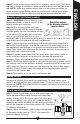
• Locate motion sensor so motion moves across
detection zone (K).
• Locate sensor away from heat producing sources to
prevent false triggering. Also, be very careful not to
include objects such as windows, white walls and water
in the detection zone whenever possible.
• Locate sensor away from moving objects such as street traffic.
Installing your landscape motion sensor transmitter
Step 1: Choose a desired location in your yard for landscape motion sen-
sor that has a clear view of driveway, walkway or area where motion is to
be detected. The landscape motion sensor will transmit up to 100 feet in
most cases, therefore, it must be located within this range from floodlight
receiver (a closer distance will achieve more consistent performance).
Step 2: Contact your local Utility Company to be sure that there are no
buried utilities in the selected installation site before installing spike. Adjust
installation site until a safe location has been found. Do not continue until
this step has been completed!
Step 3: Safety glasses must be worn during this installation step.
Place pointed end of mounting spike (J) on ground in approved
installation location. Using hammer/mallet drive mounting spike
into ground making sure that spike is as close to vertical as pos-
sible. Do not drive spike in ground any further than first horizontal
flange from the pointed end.
Step 4: Slide bottom end of post over top end of spike making
sure that vertical ribs on spike slide in between vertical ribs inside
of post. Holes on post align with holes in spike (L). Post will stop
with bottom of post at the top of largest horizontal rib on spike.
Step 5: Install both post mounting screws through holes in side
of post to secure post to spike.
Step 6: Loosen two screws on top flange of post and
point arrow towards center of desired detection area.
This could require removing the screws and installing
them again if slotted holes will not allow arrow to point
to center of desired detection area (M).
Step 7: Remove battery cover from driveway sensor head (A) by removing
screw from recessed hole in center of back cover. Install (4) "AA" alkaline
batteries in battery compartment making sure that batteries are installed in
the correct orientation as shown on printed diagram in battery area. Allow
60 seconds after batteries are installed before testing (see How to operate
your fixture for correct settings before replacing cover). Replace back cover
by aligning groove around perimeter of back cover with rib around perime-
ter of battery compartment while making sure that recessed screw hole
aligns with screw boss. Replace screw in recessed hole in battery cover
and tighten to secure cover to sensor housing.
4
ENGLISH
K
L
M