SD2 Speech Dialler Installation and Operator’s Manual
CONTENTS OVERVIEW ................................................................. 3 MAIN FEATURES.......................................................... 4 SD2 LAYOUT ............................................................... 7 INSTALLATION REQUIREMENTS .................................... 8 PCB LAYOUT ............................................................... 8 CONNECTIONS TO THE CONTROL PANEL ........................ 9 CONTROL PANEL CONNECTION TABLE .........................
Overview Introduction 3
Main Features The SD2 provides a means of communicating alarm information from a control panel to either a standard or a mobile telephone. The unit normally connects to an alarm control panel, which provides the necessary power and battery back up. Triggers: The SD2 has four trigger inputs. You can assign a voice message and/or a text message to each input. The unit can also send a message/or a text message when the triggers have been restored.
Text Messages: The SD2 can also send text messages to mobile telephones using the SMS text service (Short Message Service). The unit does this by calling a SMS service centre, which takes the text message from the SD2 and forwards it to the contact's mobile telephone.
Listen-In Mode: The SD2 has a listen-in mode, which switches an internal microphone to the telephone line so that you can hear activity at the protected site. The contact can activate the listen-in mode at the time of receiving a voice message or by calling into the SD2 and using the Remote Access feature. Talkback Mode: The SD2 has a talkback mode, which switches the internal loudspeaker to the telephone line so that you can talk to the protected site.
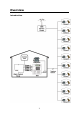
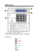
SD2 Layout 1. Two-line backlit LCD display 2. Keyboard 3. Green LED follows the programming of output 1. (See page 30). 4. Red LED follows the programming of output 2. (See page 30).
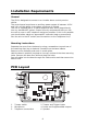
Installation Requirements General The SD2 is designed to connect to an intruder alarm control panel or similar. The control panel must have an auxiliary power output of between 10.5V and 14V, and the ability to provide a minimum of 100mA. The unit is supplied with a 2-metre telephone lead, which plugs directly into any standard BT socket. Cooper Security recommends that you site the unit as near to a BT telephone socket as possible.
Connection terminals on the SD2 are described as either “Safety Extra Low Voltage” circuits (SELV) or “Telecommunications Network Voltage” circuits (TNV). It is important that the TNV connections are only connected to the PSTN, and SELV circuits are only connected to designated SELV circuits. Interconnection circuits should be such that the equipment continues to comply with the requirements of 4.2 of EN 41003 for TNV circuits and 2.3 of EN 60950 for SELV circuits, after making connections between circuits.
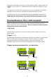
Trigger inputs programmed for -ve operation Trigger inputs A B C TRIG D TAMPER OP1 OP2 12V 0V To 12v Auxiliary supply N.O. Loop Trigger inputs A B C TRIG D TAMPER OP1 OP2 12V 0V N.C Loop To 12v Auxiliary supply Tamper These terminals provide tamper protection for the SD2 and should be connected to the auxiliary tamper circuit on the alarm control panel. OP1 & OP2 Two programmable switched -ve @100mA outputs.
Control Panel Connection Table The table below shows connection details for various alarm control panels: Control Panel Trigger Inputs Trigger Polarity 12V 0V -ve 13V+ 13V- B -ve 13V+ 13V- N/A B -ve 13V+ 13V- N/A N/A B -ve 13V+ 13V- N/A N/A S- -ve Aux + Aux - CQR Premier 9 FA* PA IA +ve DA Abacus 6 N/A N/A Bell -ve Aux 12V +12V Aux 0V -0V DA Abacus 8 N/A N/A Bell -ve +12V -0V Gardtec 500 Series Gardtec 800 Series Menvier TS400/410 Menvier TS Range Pyronix Oct
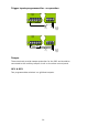
Connections to the Telephone Line The easiest way to connect the SD2 to the telephone line is to use the telephone lead that is provided with the unit as shown below: A B A1 A2 Standard BT telephone plug However, if the lead is not long enough or a serial connection is required the SD2 can be hard wired to the telephone socket as shown below: 12
Commissioning Once all necessary connections have been made to the Speech Dialler, clip the cover on to the base taking care not to trap any cables. Hold down 9 and reconnect the power to the speech dialler. The SD2 displays the factory-reset menu: At this point: Pressing [ defaults the SD2 to factory settings. Pressing ] cancels the factory reset. To select the programming mode enter the default passcode of 1234. The display shows “ ¬¦ENT to Select Phone Numbers”.
Accessing the Programming Menu When the SD2 is in standby mode the display shows the following: To access the programming menu you must enter the operator’s passcode (default 1234). The display shows the first menu option. You can scroll up and down through the menu options using the scroll key, or jump to a menu by pressing the relevant hot key. For example, to select the Call Log menu press 9.
Programming Menu Options Once you have entered the programming menu, the following options are available: 1 Contact Details. This menu allows you to edit the dialler’s contact name, telephone numbers and call types. For more information, refer to page 16. 2 Messages. These menus allow you to Record Voice and customise Text Messages. For more information, refer to page 19. 3 System Options. This menu allows you to edit the dialler’s system options. For more information, refer to page 23.
Contact Details The SD2 can store up to 10 contacts; each contact is assigned the following parameters: Name Up to 16 characters can be assigned to the contact name. Telephone No. Each contact’s telephone number can have up to 24 digits. When programming the contact’s telephone number the key can be used to insert the following command characters: * Star: Inserts a * into the telephone number. # Hash: Inserts a # in the telephone number.
To Add/Change contact details From the main menu press the ¬and ¦ keys or press 1 to select contact details menu: 1. Press [ to select: 2. Press the up & down keys or 1~8 to select the required contact, e.g.: 4: 3. Press [ to select: 4. Use, the text editing keys (see page 52) to enter the contact’s name (maximum of 10 characters). 5. Press [ to accept: The contact’s telephone number is now displayed.
6. Press [ to edit telephone number: 7. Use the keys 0 ~ 9 to enter the telephone number. E.g. 01275 555123. The key can be used to insert special characters * #, If a telephone number is already programmed, or a mistake is made during programming you can clear the last digit by pressing the Clear key. Press [ to accept: The display now shows the contact type: 8. Scroll with the ¬and ¦ to change the contact type e.g. Text. 9.
Messages Recording Messages The SD2 has eight voice messages, and one common site message; each message can be up to 30 seconds long (in long play mode). The unit has an internal microphone and loudspeaker, which are used to record and playback the voice messages. Messages should be recorded to reflect the type of alarm that is being triggered, e.g., if “trigger input 1” is connected to a smoke alarm then “message 1” should state that there is a fire alarm at the premises.
4. Press to start recording. Speak clearly at the unit. The display will show how much time has elapsed: 5. Press to stop recording: 6. To play back the message press key. The message will then be played back through the internal loud speaker. 7. Repeat steps 3 – 6 for other voice messages. 8. If you wish to re-record or delete a message press the clear key. Press ] key to exit this menu.
To Customise Text Messages The SD2 can send text messages to mobile telephones using the SMS text service (Short Message Service). The unit does this by calling a SMS service centre, which takes the message from the SD2 and forwards it to the contact’s mobile telephone. The unit can store up to eight 32-character Alarm messages. When the unit sends a text message, it adds the “site message” with a time and date stamp (see Adjusting the Date and Time.).
5. Press [ to edit: 6. Use the text editing keys (see page 52) to enter the text message: 7. Press [ to accept. Repeat steps 3 – 8 for other messages or press ] to exit this menu.
System Options Editing the System Options Menu From the main menu press ¬and ¦ or 3 to select the following system options: 1. Press [ to select: 2. Press [ to edit. From this menu press the ¬or ¦ keys to select the following options: - Remote Option: If enabled (ON) the SD2 will allow remote access through the telephone network. (See page 48). If disabled (OFF) the SD2 will not allow remote access (default).
Note: this message will not require an acknowledgement. Report Time: This option sets the time that the Auto Reporting Message is transmitted (Default 12:00 hours). Scroll with ¬and ¦ keys to select the required hour. SMS Call Number: This option allows the editing of the default SMS service centre used by SD2 to send a text message. The SD2 defaults to the O2 SMS centre. Listed below are other service centres that can be used: Service Provider O2 - UK One2One- UK Vodafone Mobiles - UK Telephone No.
answer the incoming call and allow the caller to use the ‘remote access feature’, see page 48. If disabled (OFF) the SD2 will answer all incoming calls after the number of rings programmed for the Ring Count, see option below. Flash On Message: If enabled (ON) the SD2 will flash the display backlight on and off when message is waiting (default). Listening to the message cancels the display flashing. If disabled (OFF) the SD2 will not flash the display backlight.
Long play: If enabled (ON) the recordable messages have a maximum record time of 30 seconds. If disabled (OFF) the recordable messages have a maximum record time of 15 seconds; also the speech is of a higher quality, (default). Line Fault: If enabled (ON) the SD2 logs any line fault and displays ‘line fault’ on the display; it also produces an audible tone every 60 seconds. Entering programming mode will silence the audible tone if the line fault persists.
4. Press [ to accept. Press ] to exit this menu. To Change Remote Access Code Remote access to the SD2 can be protected by a 4-digit passcode (default 5678). From the change access code menu press either the ¬ or ¦ keys until the display shows change remote access code. 1. Press [ to select: 2. Enter new passcode, e.g. 2580: 3. Press [ to accept. Press ] to exit this menu.
Acknowledgement and Abort Options Abort options Occasionally, you may trigger your alarm by accident and cause the SD2 to send an unwanted call. When this happens the unit can be aborted. When a call is aborted the SD2 immediately hangs-up and returns to its normal standby mode. The trigger inputs can be programmed to one of the following options: None Trigger inputs cannot be aborted, (default). Passcode Only The selected trigger input can only be aborted by entering the operator’s passcode into the SD2.
2. Press [ to select: 3. Scroll with the ¬and ¦ keys to select the required abort option followed by [. Press ] to exit this menu. Clear by Options Once the SD2 has made its call and delivered its message, it requires a signal to say that the message has been successfully received and accepted. NB: If a call is not accepted, the SD2 will dial the following programmed contact number. To accept a call the recipient MUST press the number 8 button on their telephone.
2. Scroll with the ¬ and ¦ keys to select the required Clear By option followed by [. Press] to exit this menu. Output Options The SD2 has two programmable outputs that can be accessed remotely and used for a wide variety of functions. Each output can be programmed to one of the following functions, e.g. switching on lighting or heating/ventilation systems. OFF: The output remains off at all times.
Phone Line Fault: This output type will activate when telephone line connected to the unit has a fault, i.e. line disconnected or no line voltage after 50 seconds. Line in Use: This output type activates when the SD2 is using the telephone line. Call Active: This output type activates when the SD2 is active, i.e. after the unit has been triggered. The output de-activates once the unit has dialled all its contacts or the call is aborted.
To Program Outputs 1 and 2: From the main menu press ¬and ¦ or 6 to select the Program Outputs Options: 1. 2. Press [ to select: Scroll with the ¬and ¦ keys to select the Output 1 or 2 followed by [. e.g. Output 2. 3. 4. Scroll with the ¬ and ¦ keys to select the output type required e.g. Message Waiting followed by [. Repeat steps 2 and 3 for the other output or press ] to exit this menu.
Call Routing Options Messages A, B, C or D can be programmed so that they only report to certain telephone numbers i.e. Message A might report to telephone numbers 1, 3, 4, 5, 6, but NOT to number 2, 7 & 8. Editing Call Routing: From the main menu press ¬ and ¦ or 7 to select the Edit Call Routing Options: 3. 1. Press [ to select: 2. Press [ to select: Scroll with the ¬ and ¦ keys to select which message requires editing e.g. C. 4.
5. Repeat steps 3 and 4 for further triggers or press ] to exit this menu. There is a further advanced option that allows a ‘Restore message’ to be sent when a trigger input returns to its normal state i.e. when the alarm system has been reset after an alarm activation. Edit Restore Routing: From the Edit Call Routing Option menu press either the ¬ or ¦ keys until the display shows the Trigger Restore. 1. Press [ to select: 2. Scroll with the ¬ and ¦ keys to select which message requires editing e.g.
Route Auto report This menu is used to select which contact/s will be notified by test call facility. (See auto reporting on page 23). 1. Press [ to select: 2. The display will show that auto report is routed to telephone number 1 (Default). Press keys 1 to 0 to select or deselect the required telephone numbers (0 equates to 10). NOTE: * = not routed. Press ] to exit this menu.
Set Date and Time This option allows you to adjust the SD2’s time and date. The clock is in 24-hour format and is used for providing the time and date stamp for the event log, text messaging and for the units display. NB: The clock is for a guide only. Adjusting the Date and Time. From the main menu press ¬ and ¦ or 8 to select the Set Time and Date Options: 1. Press [ to select: 2. Enter the new date i.e. 28/01/04. 3. Press [ to select: 4. Enter the new time in a 24hr format, i.e. 1700 for 5:00 pm.
View Log The SD2 has a time and date-stamped 128 event log that records the trigger input and which recipient was contacted. To view the call Log From the main menu press ¬ and ¦ or 9 to select the View Log: 1. Press [ to select: The display will show the last event. Scrolling with the ¬ and ¦keys allows you to scroll backwards and forwards through the log events. Pressing the ] key leaves the menu.
Temp High 18:19 28/01/04 The pre-set temperature high has been exceeded. Temp High Normal 18:33 28/01/04 The temperature high has now returned below the pre-set. Temp Low 03:00 28/01/04 The pre-set temperature low has been exceeded. Temp Low Normal 08:17 28/01/04 The temperature low has now returned above the pre-set. Line Fault 14:56 28/01/04 The unit has detected no telephone line for more than 40 seconds. Line Restored 15:16 28/01/04 Telephone line restored.
Test Options The SD2 has six test options. Test Messages This menu allows you to test the voice messages. The unit will call the selected contacts and play the selected voice message. To Test Messages: 1. From the main menu press ¬ and ¦ or 1 to select the Test Options menu: 4. 5. 2. Press [ to select: 3. Press [ to select: Press ¬ and ¦ to select which message is required i.e. 4. Press 1 to 0 to select which contact requires the test message to be sent.
6. Press [ to start the test. To cancel the test at any time press the ] key: 7. Dialling the contact’s telephone number: 8. 9. Ringing detected: Contact has answered the call and the unit playing the voice message: 10. Contact has acknowledged the call by pressing the number 8 key on their telephone: 11. Test call finished: Repeat steps 3-5 for other messages or press ] to exit this menu.
Test Outputs This test menu allows you to test the SD2’s outputs: From the Test Options menu press ¬ and ¦ or 2 to select Test Outputs menu: 1. 2. Press [ to select: Press either 1 or 2 to Test Outputs 1 and 2, e.g. 2: The LEDs OP1 and OP2 glow when the outputs are active. 3. Deselecting or ] returns the outputs back to normal.
Test Triggers This Test Menu allows you to test the SD2’s trigger inputs: From the Test Options menu press ¬ and ¦ or 3 to select Test Outputs Menu: 1. 2. Press [ to select: Activate the SD2 trigger inputs. The display will now show the current status of the inputs, i.e. trigger B is active: 3. Press ] to exit this menu.
Test Line This Test Menu allows you to test the SD2’s telephone line status: From the Test Options Menu press ¬ and ¦ or 4 to select Test Outputs Menu: 1. Press [ to select: Test Power Supply This Test Menu allows you to test the SD2’s supply voltage: From the Test Options Menu press ¬ and ¦ or 5 to select test battery voltage: ¬¦ Ent to Select Test Supply 1. Press [ to select: Test Supply 12.1V 2. It is recommended that the normal running voltage should not go below 12volts.
Leaving Programming In programming mode the SD2’s trigger inputs are disabled and therefore the unit will not call out in the event of an alarm. NB: Please note for correct operation it is necessary to exit the programming correctly. To Exit Programming Mode: From the main menu press ]: The display will ask for confirmation to exit programming: Press [ to leave programming mode.
User Guide Voice Message Calls The SD2 requires a call acknowledgement in order to confirm that the recipient has accepted the call. All contacts must be informed that to accept a call they must press number 8 on their telephone. If a call is not acknowledged by pressing 8, the SD2 will proceed to contact the next programmed number. How to Acknowledge a Voice Message: When the telephone rings, answer the call as normal. Listen to the voice message. The message is repeated 3 times in total.
Recording and Playing a Memo Locally The SD2 has an in-built memo facility to record voice messages at the keypad. Once recorded the display will indicate that there is a memo message waiting. To Record A Memo Message Ensure the unit is in normal mode: Press to record the memo. Speak clearly at the unit. The display will show how much time has elapsed: Press to stop recording. The display will now indicate that there is a memo waiting.
To play the memo again press or press the clear button to delete the memo.
Using the Remote Access Feature The Remote Access feature can be used to record messages remotely, listen into the property after an alarm message, and to toggle outputs to turn on lighting etc. This facility is accessed by one of the following methods: Dial in for Remote Access This method requires you to call into the SD2 in order to select the Remote Access Menu. If the “Remote Option” is enabled (see page 23) you will need to enter the Remote Access Code (see page 27).
To Acknowledge a Call and Select Remote Access Mode: When the telephone rings, answer the call as normal. Listen to the voice message. The message is repeated 3 times in total. When you have understood the message, you can select the Remote Access Menu at any time by pressing the * key on your telephone (please note that pressing 8 key will accept the call without entering the Remote Access mode.
Listen-in & Talkback Mode These Remote Access commands allow you to listen-in and talk to the remote site using your telephone handset. To Select Listen-in/Talkback Mode: Establish a Remote Access connection with the Speech Dialler. Press * 3 on your telephone. You can now listen into the premises. Press 3 on your telephone to switch between the Listen-in and Talkback mode. The Listen-in/Talkback mode can also be toggled at site by pressing [ key.
Record/Play Voice Messages These Remote Access commands allow you to record and playback voice messages 1 - 8 through your telephone handset. These commands are only available if the ‘Remote Access Code’ option is enabled (see page 27). To Record/Play a Voice Message: Establish a Remote Access connection with the SD2. To record a Voice Message press [*] 4 followed by the message number 1 to 8 on your telephone. You will hear a short beep. Talk clearly into your telephone handset.
Text Editing Keys Text is programmed in a similar way to mobile phones. Characters are selected by pressing the corresponding key the appropriate number of times (to select a character on the same key, wait for the cursor to automatically advance). The table below shows the keys to use and the characters that are assigned to them: Key Character 1 .
Specifications Supply Voltage: 10.
Quick Reference 54
Quick Reference 55
Declaration of Conformance Cooper Security Ltd issues this certificate to certify that the equipment known as: SD2 Complies with the following directive: 1995/5/EC R&TTE Directive by the application of the following harmonised standards: BSEN 50130-4 TBR21 BSEN 60950 Signed Stewart Taylor, Technical Director Date: 31 March 2004 © Cooper Security Ltd. 2004 Every effort has been made to ensure that the contents of this book are correct.