INSTALLATION GUIDE HARDWIRED CONTROL UNIT
9752 Hardwired Control Unit Installation Guide This document applies to control panels using software version 4.x and 5.x. © Cooper Security Ltd. 2009 Every effort has been made to ensure that the contents of this book are correct. However, neither the authors nor Cooper Security Limited accept any liability for loss or damage caused or alleged to be caused directly or indirectly by this book. The contents of this book are subject to change without notice. Printed and published in the UK.
Contents 1. INTRODUCTION.......................................................................................... 1 About this Manual ........................................................................................................................................1 Features of the Control Unit .........................................................................................................................2 Elements of the IAS ...................................................................
Contents 9752 Installation Guide List of Figures Figure 1. Elements of an Intruder Alarm System..........................................................................................4 Figure 2. 9941 and 9943 Keypads ...............................................................................................................5 Figure 3. Control Unit PCB Layout.............................................................................................................11 Figure 4.
1. INTRODUCTION About this Manual This manual is divided into three chapters: 1. Introduction: this describes the parts of an Intruder Alarm System (IAS) based on the 9752 control unit. 2. Technical description: this defines the operating parameters of the different parts of the system. 3. Installation: this explains the tasks involved in installing an IAS using the 9752 control unit. The control unit is designed to be fully programmable to suit individual user and site requirements.
1. Introduction 9752 Installation Guide Features of the Control Unit The control unit provides: ° Connections for 8 Fully Supervised Loop (FSL) zones or 8 Closed Circuit Loop (CCL) zones with a common tamper. Separate expander units enable a further 24 zones to be connected: a combination of wired and radio expanders can be used. ° Connections for 3 fully programmable panel outputs. ° A connector for downloading from a local PC. ° A 4-wire bus for keypads, a keyswitch and hardwired or radio expanders.
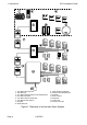
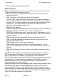
9752 Installation Guide 1. Introduction Elements of the IAS An IAS comprises a control unit in a shielded case, with 1 to 4 separate keypads and various detectors, transmitters and other devices connected to programmable zones. If required, a keyswitch can be connected to a zone. Each control unit has zone connectors on its printed circuit board (PCB).
1. Introduction A B 1 C 2 5 6 8 9 B 2 3 5 6 7 8 9 1 2 3 4 5 6 7 8 9 1 2 3 4 5 6 7 8 9 B A 0 C 1 4 A D 3 4 7 A 9752 Installation Guide D 0 C B D 0 C D 0 1. 723r EUR Telecommand 2. 726r EUR PA 3. 714r EUR wirefree Passive Infra Red detectors 4. RFX radio expander 5. 735r EUR universal transmitter 6. 720r EUR smoke detector 7. Keypads 8. Wired detectors 9. 9954 hardwired expander 10. Passive Infra Red detectors 11. Keypads 12. Door contacts 13.
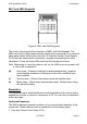
752 Installation Guide 1. Introduction 9941 and 9943 Keypads A B C 1 2 4 5 6 7 8 9 D 3 0 Figure 2. 9941 and 9943 Keypads The control unit supports the connection of 9941 and 9943 keypads. The 9943 has a built-in wide-area proximity reader and connections for an external panic alarm switch. Both have a two-line 16-character Liquid Crystal Display (LCD) that can display alarm information, programming settings and other information. There are three LEDs that have the following functions.
1. Introduction 9752 Installation Guide 2. Two-wire Fully Supervised Loop (FSL). Radio Expanders Radio expanders enable you to connect wirefree devices to the control unit. They can work with the following devices: ° 703r. Four channel programmable transmitter, when used in two door contact mode only. ° 710r. A compact, long range, two button PA transmitter. ° 713r and 714r. These are Passive Infra-Red (PIR) movement detectors.
9752 Installation Guide 1. Introduction Partitioned or Single System During installation, the Installer can configure the system as a partitioned system or as a single system. In a single system, the control unit has one full set level (security level A) and three part set security levels (levels B, C and D). Users can set only one level at a time. Level A sets the whole system. Levels B, C and D set parts of the system. The Installer allocates zones to levels, but all keypads operate the entire system.
2. TECHNICAL DESCRIPTION Control Unit Specification General Environmental Security Operating temperature Humidity Dimensions Weight Internal Clock Class 2 EN50131-1 or PD6662 Grade 2 -10° to +55°C 96% RH 300mm W, 390mm H, 95mm D 5.0 kg ±10 minutes over one year (depending on the accuracy of the mains supply frequency). Radio detector differs 16,777,214 (224 -2) Suitable for use in a system that is designed to comply with EN50131-1, ACPO-IAS Policy, NSI NACP14.
9752 Installation Guide 2. Technical Description Standby battery (not supplied) 12V rechargeable lead-acid, gel-type battery. Low battery voltage cutoff = 10V. Recommended manufacturers: Yuassa, Yucel or Fiamm. Note: Grade 1 and 2 compliance requires the panel to continue for a minimum period of 12 hours on a standby battery. To calculate the minimum capacity battery to achieve this requirement, determine the total current taken by external devices and the panel and multiply by 12.
2.
9752 Installation Guide 2. Technical Description Control Unit PCB Layout Figure 3 shows the layout of the PCB used in the control unit. 13 1 12 11 2 3 10 4 9 8 7 6 5 1. Outputs (2 voltage free; 1 open collector) 2. AUX power 3. Lid tamper connector 4. Zone connectors 5. Keypad and expander bus (bus 2 not fitted) 6. Telephone line terminals for built-in communicator 7. Telephone line socket for built-in communicator 8. Local Downloader connector 9. NVM Reset pins 10.
3. INSTALLATION Caution: Always remove mains power before opening the case lid. Do not work inside the control unit with mains power present. Overview A typical installation comprises the following main steps: 1. Survey the site and decide on positions for wired detectors, 9954 wired expanders, control unit, keypads, external and internal sounders. As part of the survey ask the users what facilities they need. 2.
3. Installation 9752 Installation Guide Cabling for Keypads and Expanders Cooper Security recommends that you use 8-core 7/0.2 or 16/0.2 alarm cable for wiring keypads and expanders. You can connect the keypads and expanders in either a star or bus configuration (see Figure 4). If you intend to use long cable runs, Cooper Security recommends that you use star wiring with no more than 200m of cable per branch. Control Unit 200m 200m 200m 200m 200m Distribute devices along cable for better performance.
9752 Installation Guide 3. Installation It is possible to extend the keypad cable run by using additional power supplies, but only up to the recommended maximum of 200m. When carrying out the cabling, there are two important points to remember: 1. Do not connect anything other than keypads or expanders to the bus. The keypad bus power supply is limited to a maximum of 400mA. 2. Check between 0V and 12V on the keypad bus at the point furthest from the control unit: the voltage must be at least 12.
3. Installation 9752 Installation Guide Fitting the System Fitting the Control Unit Case 1. 2. 3. 4. Remove the control unit case from its packaging. Remove the front screws and slide off the case lid. The upper part of the case back has a central keyway. Mark and drill a hole for the keyway. Temporarily fix the case back to the wall. Mark the position of two more fixing holes, remove the case back and drill the holes.
9752 Installation Guide 1. 2. 3. 4. 6. 3. Installation Select which cable entry you are going to use and break out the appropriate plastic sections. Hold the backplate in place against the wall and mark the position of one fixing hole. Drill and plug the hole, and screw the backplate to the wall. Do not tighten the screw completely home. Make sure the backplate is level and mark, drill and plug another fixing hole. Tighten the fixing screws.
3. Installation 9752 Installation Guide Connect the 21VAC lead from the mains transformer to the main PCB. See Figure 3 for the location of the 21VAC connector. Caution: Do not apply mains power at this point. Do not work inside the control unit case when mains power is present. Keypads Connecting Keypads Figure 7 shows the connections for keypads. Use the "ET" connector terminals on the keypad PCB to connect an exit terminate button or lock switch.
9752 Installation Guide 3. Installation Keypad Addressing The control unit is supplied with one keypad. If you have fitted more keypads, each one must be given a separate "address". Links LK2 to LK4 set the keypad address, as shown in Figure 9. Keypad 1 Address Keypad 2 2 2 2 3 3 3 4 4 4 Keypad 3 Keypad 4 2 2 3 3 4 4 ON BACKLIGHT ON BACKLIGHT Backlight ON ON BACKLIGHT Backlight OFF Figure 9.
3.
9752 Installation Guide 3. Installation If you require more zones, fit one or more expanders as explained on page 22). There can be up to 24 zones on expanders. Control Unit Zones 8 8 Wiring Type four-wire CCL with common tamper two-wire FSL CCL Connections Figure 11 shows how to connect four-wire CCL zones. Tamper loop Global Anti-tamper Zone 1 Zone 2 Alarm contacts Zone 1 1 2 Zone 3 Zone 4 Zone 5 Zone 6 Alarm contacts Zone 7 Zone 8 Zone 2 Figure 11.
3. Installation 9752 Installation Guide 4K7 Alarm contacts 2K2 EOL Zone 1 Tamper contacts 4K7 1 2 Zone 2 Alarm contacts 2K2 EOL Tamper contacts Figure 12. FSL Connections 4k7 Yellow Violet Red Gold 2k2 Red Red Red Gold Figure 13. Colour Code for FSL Resistors Anti-Masking Zone Connections Note: Connecting an anti masking detector to the 9751 does NOT make the 9752 a Grade 3 control unit.
9752 Installation Guide 3. Installation Anti-mask 4K7 2K2 Alarm 2K2 Zone Resistance Note: Depending on the sensor, a 4K4 resistance means either "masked" or "fault". Use command 88 to specify which reporting method to use. All sensors with anti-masking contacts must use a 4K4 resistance for the same meaning (masked or fault). Open Circuit Tamper Alarm 9.1k Masked 6.9k Alarm 4.4k Sensor failure/Fault/Masked 2.
EOL 9752 Installation Guide FSL 3. Installation Four-wire CC Two-wire FSL Two-wire EOL 2 AT5 CCT2 AT6 EOL CCT1 FSL 1 AT1 CCT5 AT2 CCT6 CCT3 AT7 CCT4 AT8 AT3 CCT7 AT4 CCT8 2 3 4 6 5 3 4 0V 12V CLK DATA 1. Zone connectors 2. Lid tamper switch 3. Spare connectors (not connected) 4. Keypad bus 7 5. Address jumpers 6. Zone connectors 7. CCL/FSL/EOL Figure 15. 9954 Expander RFX08/RFX16 Radio Expander The RFX08/RFX16 are a Class VI radio expanders.
9752 Installation Guide 3. Installation 7 1 2 8 3 9 4 10 5 6 12 11 14 0V 12V CLK DATA 13 15 1. 2. 3. 4. 5. 6. 7. 8. Red "Fail" LED Green "Pass" LED Sounder 2 x 7-segment display Select button Delete button Built-in aerial Tamper switch 9. 10. 11. 12. 13. 14. 15. Radio section Learn sensor Supervision jumper Jamming response jumper Address jumpers Bus connector Cable entry Figure 16.
3. Installation 9752 Installation Guide FSL EOL When fitting a 9954 hardwired expander, make sure that you place the jumper link on the expander in the correct position to select either four-wire CCL, or two-wire FSL (see Figure 18). Four-wire CC Two-wire FSL Figure 18. Link Positions to Select Wiring Method Once you have connected an expander, refer to the instructions supplied with it for connecting hardwired detectors or "learning" radio detectors as appropriate.
9752 Installation Guide 3. Installation Programming Outputs Control unit panel outputs can be programmed using the commands shown in the table below. Open collector outputs are of a "pull down" type that provides negative-applied control signals; the system adjusts the output polarity when you select the output type.
3. Installation 9752 Installation Guide CC Wiring CCT(n) 4k7 FSL Wiring 2k2 CCT(n) Fixed Keyswitch (KF) Keyswitch CC FSL OFF Closed 2k2 ON Open 6k9 Momentary Keyswitch (KM) Keyswitch CC FSL Operate Close-Open- 2k2-6k9-2k2 Close Operate Close-Open- 2k2-6k9-2k2 Close System Unset Set System Unset Set Figure 21. Connecting a Keyswitch Note: If you connect a keyswitch as a zone it can be used to set and unset the level to which the zone is assigned.
9752 Installation Guide 3. Installation Communicator Connecting the Communicator The control unit has an internal communicator on its main PCB. This is an auto-dialling modem. If necessary, a standalone communication device can be connected through a wiring harness to interface pins on the main PCB (this is known as a plug-by communicator).
3. Installation 9752 Installation Guide Line Monitoring for the Internal Communicator The control unit provides a line monitoring function to check that a telephone line connected directly to the control unit is working, and to indicate a line failure if it is not. While enabled, this function continually checks the line voltage to ensure that the line is connected. If it detects a failure, the system gives the Line Fault Response selected with Command 106.
9752 Installation Guide 3. Installation Usage other than approved usage or failure to comply with the installation and programming instructions may invalidate any approval given to the apparatus if, as a result, the apparatus ceases to comply with the standards against which approval was granted. Note the approval label on the main PCB. In the event of problems you should contact your equipment supplier in the first instance.
3. Installation 9752 Installation Guide 9 8 7 1 6 5 4 3 2 1. Main connector (SELV) 6. Wire in comms connector (SELV) 2. Keypad connector (SELV) 7. Lid tamper connector (SELV) 3. Telephone line connector (TNV) 8. Battery connector (SELV) 4. RJ11 connector (TNV) 9. 21VAC from transformer (SELV) 5. Local Downloader connector (SELV) Figure 22.
9752 Installation Guide 3. Installation Connecting the Telephone Line Connecting the telephone line directly to the terminals on the internal communicator, or indirectly through other apparatus, can produce hazardous conditions on the telephone network. Always seek advice from a competent telephone engineer if in any doubt about connecting to these terminals.
3. Installation 9752 Installation Guide Fitting a Plug-by Communicator The control unit can be fitted with a communicator or speech dialler (for example, the Scantronic 8400, 8440, 660 or RedCare STU). Figure 24 shows the connections for the communications wiring harness. Com Connector Cable, Part No.
9752 Installation Guide 3. Installation Line Monitoring for a Dual-Path Communicator If a standalone dual-path (landline and mobile) communication device, such as a RedCARE STU, is connected to the plug-by connector, you need to do the following to obtain correct line fault reporting: 1. Wire a control unit output programmed as type "ATS Test" to the ATS Test input of the communicator. Invert the sense of the output at the control unit if a "positive applied" input sense is used at the communicator. 2.
3. Installation 9752 Installation Guide Notes: 1. With software versions earlier than 5.xx.xx key in 0 followed by the default Engineer Code 7890. 2. You do not have to remove the case lid. The display shows: Installer Mode You are now in installer (programming) mode. The Programming Guide explains how to program the system. Cooper security recommend that at this point you return the system to its default settings using Command 98.
Index 9954 PCB layout...........................................................23 Access code..............................................................7, 35 Auxiliary output ...............................................................9 Battery fitting ........................................................................35 specification...............................................................9 Bell tamper return.............................................................
Index 9752 Installation Guide Transmitter PA transmitter ..................................................... 6, 10 universal ............................................................. 6, 10 Universal transmitter ................................................ 6, 10 Weight ............................................................................ 8 Page 38 11976870 Zone CCL ......................................................................... 21 FSL...........................................
9752 Installation Guide Index 11976870 Page 39
Cooper Security Ltd. Security House Vantage Point Business Village Mitcheldean Gloucestershire GL17 0SZ www.scantronic.co.uk Product Support (UK) Tel: +44 (0)1594 541979 Available between: 08:15-12:30 and 13:30-17:00 Monday to Friday. Product Support Fax: +44 (0)1594 545401 Part Number 11976870 Declarations of conformance to standards can be obtained from our Web site, www.coopersecurity.co.