Security System Installation and Programming Guide
© Cooper Security Ltd. 2009 Every effort has been made to ensure that the contents of this book are correct. However, neither the authors nor Cooper Security Limited accept any liability for loss or damage caused or alleged to be caused directly or indirectly by this book. The contents of this book are subject to change without notice. Printed and published in the U.K. This manual applies to software used in the i-on16 control unit with version 1.00 software.
i-on16 Contents 1. Introduction ...................................................................1 Overview ......................................................................... 1 End Station and Keypad ..................................................... 2 Opening the End Station Case............................................................2 End Station PCB ..............................................................................3 Keypad Controls and Displays ..............................
i-on16 Leaving the Installer Menu................................................ 28 Restoring the Access Codes (1st stage Reset) ...................... 28 Restoring All Factory Default Programming ......................... 29 Detectors/Devices ........................................................... 30 Detectors ..................................................................................... 30 Edit Zones ....................................................................................
i-on16 1. Introduction Overview The i-on16 is the control unit for a wirefree alarm system intended for domestic and light commercial use. The control unit comprises an end station and separate keypad. The end station has an ABS plastic case which contains the radio transceiver, power supply and backup battery. Connected to the end station by standard alarm cable is the keypad. The keypad allows the end user to set and unset the system, and the installer to configure the control unit.
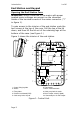
Introduction i-on16 End Station and Keypad Opening the End Station Case WARNING: When connected to the mains with power applied mains voltages are present on the shrouded heads of the terminal screws of the mains connector (“7” in figure 1). To gain access to the interior of the end station undo the two screws at the top of the case. Pull the top of the lid down, and then lift the lid out of the retaining lugs at the bottom of the case (see Figure 1.) Figure 1 shows the interior of the end station.
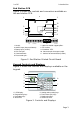
i-on16 Introduction End Station PCB Figure 2 shows the controls and connectors available on the end station PCB. 1 1 11 2 10 9 8 7 6 3 4 5 14V4 0V 12V AUX 1 2 3 4 OUTPUTS TR 1. Aerials. 2. 20VAC Input (from transformer). 3. Battery input (12VDC). 4. Kick start pins. 5. Connector block. 6. Reset codes pins. - LS + 0V 12V A BUS B 0V 0V 12V 12V AUX AUX 7. Holes for module support pillars. 8. RF receiver. 9. “Heartbeat” LED. 10. Connector pins for tamper switch. 11.
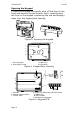
Introduction i-on16 Opening the Keypad To open the keypad first gently prise off the trim on the front and remove the two screws. Next, carefully lever the front of the keypad (containing the pcb and display) away from the keypad rear housing. Figure 4. Opening the Keypad 3 1 2 3 4 1. Central keyhole. 2. Rear tamper shroud. 3. Cable entry. 4. Fixing holes. Figure 5. Keypad Rear Housing 1 4a 4 3 2 ABCD-ON ON BACKLIGHT BRIGHT 2 4b 3 4 ET B A 12V 0V 5 1. Sounder. 2. Sounder volume control. 3.
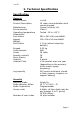
i-on16 2. Technical Specification Specification General Product name Product Description Manufacturer Environmental Operating temperature Dimensions: End station Keypad Weight: End station Keypad Case material Zones Remote controls Panic Alarms Outputs Internal Clock Log capacity Security Security Grade Radio detector differs Radio Supervision Access code Number of user codes i-on16. 16 radio zone endstation with remote keypad. Cooper Security Ltd. Class II. Tested -10 to +55°C.
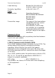
Technical Specification Code blocking Proximity tag differs Radio Radio Section Transmitter range i-on16 Blocked for 90s after four incorrect codes in series. 4,294,967,296 (232) Operating frequency 868.6625MHz Narrowband. EN 300 220-3. EN 300 330-2 Telefication The range of the transmitters compatible with this control unit depends on the environment in which they are installed. As a guideline, most transmitters will work up 200m range in free space conditions.
i-on16 Technical Specification Power Supply This product complies with the requirements of EN501316 Type A power supply at Grade 2 and environmental class 2. Mains power supply 230VAC +10%/-15%, 170mA max, 50Hz. End station psu 13.7VDC, 1.5A max End station consumption 145mA. Communicator consumption 50mA max Keypad consumption 30mA (backlight off) 45mA (backlight on) 65mA (backlight on max) Standby Battery 12V, 7Ah sealed lead acid. Standby time: more than 12 hours.
Technical Specification i-on16 Fuses The control unit has a 250mA mains fuse. Electrical Safety Conforms to EN60950-1. Compliance Statements This product is suitable for use in systems designed to comply with PD 6662: 2004 at grade 2x and environmental class II. This product complies with the requirements of 50131-3 at grade 2 and environmental class II. This product complies with the requirements of EN501316:2008 at grade 2 and environmental class II.
i-on16 Technical Specification Compatible Equipment 706rEUR-00 710rEUR-00 713rEUR-00 714rEUR-00 720rEUR-00 726rEUR-50 726rEUR-60 734rEUR-00/01 734rEUR-05/06 738rEUR-00/04 739rEUR-25 760ES I-FB01 I-KP01 I-RC01 I-RK01 I-SD01 9040UK-00 Two button PA/tilt switch transmitter Two button PA Pet tolerant PIR PIR Transmitter (Small case) Smoke Detector Transmitter Long range hand held PA Short range hand held PA CC/FSL Door Contact Transmitter (white) CC/FSL Door Contact Transmitter (brown) Spyder shock sensor (w
i-on16 3. Installation WARNING: Exposure to Radio Frequency Radiation The radiated output power of this device is below those levels considered safe by European exposure limits. Nevertheless, when fitting the product place it in such a manner as to minimise the potential for human contact during normal operation. To minimise exposure, users should be more than 200 mm from the device during normal operation Tools Required 790r signal strength meter and 734r test transmitter. Flat screwdriver (small).
i-on16 Installation As high as possible. However, do make sure that the unit is on a similar level to the other transmitters or receivers. Do NOT site the unit: In the entry or exit zones, or outside the area covered by the alarm system. Close to or on large metal structures. Closer than one metre to mains wiring, metal water or gas pipes, or other metal surfaces. Lower than two metres from the floor (ideally). Inside steel enclosures.
Installation i-on16 Protect the unit from dust and drilling debris when drilling the fixing holes. 1 1 1 1. Fixing holes. 2. Cable entries. 2 1 2 Figure 7. Fixing Holes and Cable Entries 2. Fit and Connect the Keypad Siting the Keypad Do site the keypad: Within the area protected by the alarm system. At a convenient height and location for the user. Out of sight of potential intruders.
i-on16 Installation Note: Do not site two or more keypads closer than one metre together, otherwise their prox readers will interfere and be unable to read tags. Fitting Use M5 25mm countersunk screws in at least three fixing holes when mounting the back of the keypad on the wall. Figure 8. Screw Keypad Back Box to Wall Connect Keypad to End Station Cable Type In general, the control unit requires standard 7/0.2 unscreened alarm cable for wiring to keypads.
Installation i-on16 Cable Segregation Segregate the keypad cabling from any other wiring, such as mains supply cables, telephone cables, computer network cables and R.F. cables. Use cable ties to keep cables separated. Keep the keypad cable clear of cables supplying sounders or extension loudspeakers. Connection You can connect up to two keypads to the end station. You may connect the keypads either serially, or in parallel at the end station connector.
i-on16 Installation MENU MENU A B 1 2 abc A 3 def 4 ghi 5 jkl 6 mno 7 pqrs 8 tuv 9 wxyz * 0 # 1 B 4 ghi 2 abc 5 jkl 3 def 6 mno 7 pqrs 8 tuv 9 wxyz * 0 # 4 3 2 4 3 2 4 3 2 4 3 2 Figure 10. Keypad Addressing Jumpers Backlight Control You can control the appearance of the keypad backlights and set/unset LEDs by fitting links over the appropriate jumpers on the keypad pcb (see Figure 6 on page 4 for the position of the jumpers).
Installation i-on16 Tone Volume To adjust the volume of tones from the keypad: Louder Note: This control changes the volume of non-alarm tones (for example Exit/Entry tone). The volume of alarm tones is fixed. Softer Figure 11. Adjusting Tones and Chime Volume. 3. Connect End Station to Mains WARNING: The end station should be connected to the mains supply by a qualified person.
i-on16 Installation If you wish run mains cable through the side of the case, make sure that they are horizontal for the last metre before entering the case. Mains Connection Figure 13 shows the mains connection. Connect to a suitable supply using a double pole disconnect device in accordance with EN60950-1. L N 230V ~50Hz 200mA T 400mA 250V Figure 13. Mains Connection Caution: Do not apply power at this point. 4. Connect Wired Peripherals The end station pcb provides four connectors for wired outputs.
Installation 14V4 0V 12V AUX i-on16 1 2 3 4 OUTPUTS TR - LS + 0V 12V A BUS B 0V 0V 12V 12V AUX AUX +LS -LS 12V + 0V Tamper In Tamper Out Strobe +ve Strobe -ve Trigger -ve Figure 14. Connecting Wired Peripherals Remote Loudspeaker (Optional) If you wish to add a wired Loudspeaker unit, then connect it as shown in Figure 14. Wired External Sounders (Optional) Wired external sounders differ in their methods of connection.
i-on16 Installation single wire allows you to connect the module to the 12V +ve aux supply in order to provide power for all four relays. The terminals on the edge of the card provide connections to the Normally Open, Common and Normally Closed terminals of the relays. I-ON16 3 14V4 0V 12V 1 2 3 4 TR AUX OUTPUTS - LS + 4 2 5 1 I-RC01 OP1 OP2 OP3 OP4 NO 1. Brown - OP1 2. Orange - OP2 3. Yellow - OP3 C NC 4. Blue – OP4 5. Red - 12V +ve Figure 15.
Installation i-on16 5. Fit and Connect I-SD01 (Optional) Safety Notice Figure 17 identifies connectors for Safety Extra-Low Voltage (SELV) and Telecommunications Network Voltage (TNV) circuits on the control unit's main PCB. These terms are used in accordance with the definitions in Safety Standard EN60 950.
i-on16 Installation ADSL01 Figure 18. Fitting ADSL01 to I-SD01 Note: If the telephone line is NOT shared with an ADSL modem then leave the factory fitted jumpers in place. Fit the I-SD01 to the plug on module sockets (see 11 on Figure 2 ). Figure 19. Fitting I-SD01 Module The person connecting the I-SD01 module to the PSTN must be suitably qualified. Connect the I-SD01 telephone connector (see Figure 20) ONLY to the PSTN or to other circuits designated as Telecommunications Network Voltage.
Installation i-on16 B1 A1 E C B A PSTN See Note WARNING: Telecommunications Network Voltage A, B A1, B1 E C Connect to PSTN Connect to local phone extension (if required) For added surge protection connect to a suitable protective earth. Note: (UK only) connect to ringing wire from PSTN and to ringing wire on extension phone, if fitted. Figure 20.
i-on16 Installation 6. Fit and Connect Battery Fit a 7Ah Lead Acid battery into the battery compartment in the bottom of the control unit, see Figure 21. Figure 21. Fitting the Battery Make sure that you secure the battery to the case with the strap provided. Connect the battery leads, red to the positive, black to the negative terminals of the battery. Note: Connecting the battery without mains power will not start the system.
Installation 1. i-on16 Apply mains power to the control unit. The keypads and internal sounder give an alarm tone. The heartbeat LED (see fig 2 ) starts flashing. The display initially shows: Language? English 2. 3. Press u or n to show other languages on the bottom line of the display. for example: Language? Nederlands Press Y to select the language you want. From this point on, the display operates in the selected language. If you want to change the language see page 42 .
i-on16 Installation Note that the alert LEDs round the navigation glow red. This is because the end station lid is off and the tamper is active. 7. Remove both battery and mains power. Re-apply battery power followed by mains. The sounders stop. At this point you can carry on to commission the system. See below. Note: Setting the time and date is an administrative user function. See i-on16 User Guide for instructions. 8.
Installation i-on16 3 2 1 Figure 22. Close the Control Unit 7. Leave the Installer Menu. At this point the LED around the navigation keys will still show red. This is because the system is still waiting for you to acknowledge the tamper alarm caused when you applied power for the first time. 8. Press Y. 9. Key in the default user code ‘1234’. 10. Press Y. The red LEDs should go out, and the rim of the navigation keys glow green. The system is now ready to hand over to the user. 11.
i-on16 Programming 4. Programming Entering the Installer Menu 1. 2. Make sure the system is unset and showing the standby screen (time and date). i-on16 12:00 02/01/2008 Key in the Installer access code. When delivered from the factory the default Installer access code is “7890”. The default user code is “1234”. As you start to key in the code the display shows: When you key in the last digit of the access code the display shows “Installer Menu” on the top line.
Programming i-on16 in a total of ten incorrect codes (13 consecutive digits) then the system locks you out for 90 seconds. Leaving the Installer Menu If you wish to leave the Installer Menu at any time. 1. 2. Press X until the display shows the words “Leave installer mode?”. Leave installer mode ? Press Y. to leave Installer menu. (Press X if you do not want to leave the menu.) The display shows the time and date. The system is ready for use.
i-on16 Programming The control unit loads the factory default access codes: User 1: 1234, Installer: 7890. After a short pause the keypad display shows the time and date. The red LEDs glow to show an alert that the panel lid is open. The system may start a tamper alarm. 6. Remove the short from the Reset pins. 7. Reconnect the battery. 8. Close the end station lid (to restore the tamper switch). 9. Key in 1234 to silence the sirens (if necessary).
Programming i-on16 Detectors/Devices Detectors Add/Delete Detectors To use a radio zone the control unit must learn the identity of the radio detector. To learn radio detectors select Detectors-Add/Del Detectors. 1. Use the u or n keys to highlight a free zone and press >. The display shows an “*” next to zones that already have detectors. 2. Activate the detector’s tamper. The keypad sounds a double “beep” when the control unit successfully learns the detector.
i-on16 Programming You have the choice of deleting the detector ID or of defaulting the zone. Press u or n to see each of these choices. If you select “Delete Detector ID” then the control unit “forgets” the ID of the detector, but leaves any zone programming in place. If you select “Default zone” then the control unit “forgets” the ID of the Detector and sets all the zone programming back to default values: Type = Not Used, no attributes.
Programming i-on16 Note: If you wish to leave the name unchanged then press X. The display leaves the name change screen and restores the name of the zone to its previous value. Press Y when you have finished entering text. 1 4 ghi 2 abc 3 def ABCÆÅÄ DEF 5 jkl 6 mno GHI JKL MNOØÖ 7 pqrs 8 tuv 9 wxyz PQRS TUV * 0 WXYZ # Space 0 Figure 23. Letters Assigned to Keys Zone Types When the control unit first learns a detector the zone type defaults to Normal Alarm.
i-on16 Programming Final Exit. Zones of this type must be the last detector to be activated on exit, or the first to be activated on entry. You can use zones of this type to finally set the system, or to start the entry procedure. See page 39 to set the exit mode type. Note: If you give a Final Exit zone the Part Set attribute then you can program that zone to behave like a Normal Alarm zone if the user part sets the system. See page 40. 24 Hour Alarm.
Programming i-on16 Zone Attributes The attributes available are: Chime When enabled by the user, the system gives a nonalarm warning tone when any zones programmed as ‘Chime’ are opened. This facility operates only while the system is unset. Part Set When a user presses button B (part set), the control unit sets only those zones where the Part Set attribute = “Yes”. (See also “Part Set Exit Mode” on page 40 ). Force Set Omit The user can set the system while a zone with this attribute is open (active).
i-on16 Programming The display shows a message asking you to operate the siren’s tamper. 3. Operate the siren’s tamper. The control unit learns the siren’s identity and gives a double beep. Deleting an External Siren To remove an external siren from the system: 1. Select Detectors/Devices – External Siren – Add/Del Ext Siren. The display shows two possible “memory slots” for external sirens. A slot already allocated to a siren shows a “*” at the beginning of its line. 2.
Programming i-on16 Adding a Radio Keypad To make the control unit learn the Radio Keypad’s identity. 1. Select Detectors/Devices – Radio Keypad – ADD/DEL Radio Keypad. The display shows a list of available Radio Keypads from Radio Keypad 1 to Radio Keypad 2. Each line is a “memory slot” for learning the identity of an individual Radio Keypad. If a memory slot is aleady occupied then the end of the line shows a “*” icon. 2. Select the memory slot that you wish to use.
i-on16 Programming Edit Outputs, and then select the output you wish to program. Changing Output Names When changing the output name, key in the letters from the keypad. Each number is associated with a range of letters in the same way as on many mobile phones. Figure 23 shows which letters appear on each key. To delete characters press <. If you wish to move the insertion point, then press u or n. Note: If you wish to leave the name unchanged then press X.
Programming i-on16 Strobe and Set This output is active for 10 seconds after the system has set. The output can be used to operate the strobe to give a visual indication that the system has completed setting. This output type also operates when the system is in alarm, and remains active until the user disarms the system. Setting Complete This output becomes active for 10 seconds when the control unit finishes setting.
i-on16 Programming Part Set B Name Use this option to give the Part set mode a name. The control unit displays this name to the user during setting. Exit Mode This option controls the exit mode for Full set. (For Part Set exit modes see page 40 .) The exit modes available to both Full Set and Part Set are: Timed Set. Use this option to make the system set after a delay. Use the Exit time menu (see page 39) to choose the delay. Final Door Set.
Programming i-on16 them). The exit time can take any value between 10s and 120s. Entry Time This option controls the Entry Time for both Full and Part Set. The time can take any value between 10s and 120s. Part Set Exit Mode You can select an exit mode for part set that is different from that used during full setting. Page 39 lists the exit modes available. Note: If you wish to use Final Door Set exit mode when part setting then: 1.
i-on16 Programming Strobe on Set When set to ON this option causes the control unit to activate the strobe on any siren to give three flashes after the system sets. Strobe on Unset When set to ON this option causes the control unit to flash the strobe three times on any siren after the system is unset. System Options This section of the Installer Menu contains a series of options that affect the working of the alarm system as a whole.
Programming i-on16 “No” means that the installer/maintainer can enter the Installer Menu by simply keying in their own code. Profiles This option loads a set of standard entries for all names, and sets up other options. For details see Appendix. Once you have loaded the profile you can edit any of the settings to suit an individual installation. Language The control unit can use one of several languages in its display. To change the language select System Options – Language.
i-on16 Programming The Installer code allows you to enter the Installer Menu, and carry out an Installer reset. However, the Installer code does not allow you to set or unset the system. Installer Text If required the installer can key in a text message that appears on the first line of the display in the standby screen. This could be, for example, the name of the installer’s company. See page 31 for a description of how to enter text.
Programming i-on16 Siren Time To change the length of time that the system operates the siren during an alarm select System Options-Siren Time. Note: The durations offered by the display apply to a siren wired directly to the control unit. The 760ES radio siren has one of three fixed sounder durations in an alarm: 5seconds, 3mins or 15mins. These fixed durations are designed to preserve the battery life of the radio siren.
i-on16 Programming There are three options available: Off The remote control user cannot force set the system, even if you have applied the force set zone attribute to any zones. Confirm The remote control user can force set the system. They must operate as follows: 1) the user presses the appropriate button to set the system, 2) the control unit does not start setting, 3) the user presses the same remote control button to confirm that they wish to continue setting the system.
Programming i-on16 Speech Dialler Deals with recording speech messages, selecting the alarm types that will trigger them, and selecting destinations for the messages. Line Fail Reporting Allows you to select how the control unit reports a communications failure if either the PSTN or the ISD01 fails. The control unit is designed to alert the user if it fails to complete a programmed communication.
i-on16 Programming control unit ends the call and then re-attempts to connect up to a maximum of 15 times. Alternate. The control unit reports to one of the two telephone numbers in the Phone Book. Operation: The control unit dials the first telephone number and attempts to connect to the ARC. If it fails, it will then close down and dial the second telephone number and attempt to connect to the ARC. If received and acknowledged on this attempt, the alarm transmission is complete.
Programming i-on16 Note: If you need to add a letter to the account code press the numbers keys repeatedly until the letter you want appears on the display. See page 32. Report Type To choose the report type to send to the ARC select: Reporting – Alarms – Report Type. The report types available are: Fast Format, Contact ID.
i-on16 Programming CID Reports CID reports are called ‘Telegrams’. Each telegram contains the site identification number (normally six digits long) and relevant event information. To make programming easier, the i-on16 groups CID telegrams together into Report Groups. Table 1 lists the telegrams included in each report group, and the relevant CID codes. When you enable a Report Group, then you are enabling the control unit to send any of the telegrams in that group.
Programming i-on16 Reset System reset 305 Exit timeout Exit timeout and restore 457 Omit Zone omit 573 RF supervision Zone supervision fail and restore 381 Radio keypad supervision fail and restore External siren supervision, fail and restore RF jamming Jamming fail and restore 344 RF battery psu Smoke power supply unit fail and restore 337 Panel battery Zone low battery fail and restore 384 Ext Siren low battery fail and restore 338 End station low battery and restore 302 End sta
i-on16 Programming Enabled The system rearms Channel 3 once the siren timer has expired. Once the Channel is rearmed, the system is ready to report any new alarm. The system bypasses any detectors that are still violated. Notes: If a Final Exit Zone is triggered, Channel 3 becomes active at the end of the Programmed Entry time. Send Tamper as Burg When using CID reporting this option allows you to program the control unit to send tampers as alarm.
Programming i-on16 should take place. Next, key in the hour of the day (01 to 24) on which the test call should occur.. To make test calls on one day every month select Reporting – Alarms – Static Test Call – Monthly. From the display select a number between 1 and 31 to specify the day of the month on which the call should take place. Next, key in the hour of the day (01 to 24) on which the test call should occur.
i-on16 Programming Report Triggers Messages Destinations Phone Book Home message Message 1 Dest 1 Dest 2 Dest 3 Dest 4 Y N Y N Message 2 Dest 1 Dest 2 Dest 3 Dest 4 N N N N Message 3 Dest 1 Dest 2 Dest 3 Dest 4 N N N N Message 4 Dest 1 Dest 2 Dest 3 Dest 4 N Y N Y None Fire Panic Burg Technical Alarm AC Fail Tampers Dest 1 = Tel No: 12345678 Dest 2 = Tel No: 87654321 Dest 3 = Tel No: 56781234 Dest 4 = Tel No: 21436587 Figure 24. Speech Dialler Programming.
Programming i-on16 display shows a progress bar indicating how long you have left to record. Press X to end recording. Play Message Press > to play back the message. Delete Message Press > to delete the message. When the display asks “Delete Message?” press Y. Use Lid Tamper This puts the control unit into a special mode where the tamper switch controls the recording and playback of the current message. Use this mode if the end station is an inconvenient distance from the keypad. 1.
i-on16 Programming The display then gives you a chance to key in a name for that number. The control unit will display this name in the phone book to help you remember what destination you wanted the message to go to. Press Y when you are happy that the name is correct. Note that once you have set the speech dialler call mode to “enabled” (see page 53) and assigned a report trigger to a telephone number (see below) then the control unit makes this number available in the User Menu.
Programming i-on16 Select a message from the list on the display. The control unit will show you a list of telephone numbers. If you gave a telephone number a name then the display shows the name instead of the digits of the number. Highlight a telephone number and press > until a “Yes” appears after the number. Press Y when you have finished. The control unit will send the selected speech message to every telephone number with a “Yes” next to it. Note: There are a total of five voice messages available.
i-on16 Programming Disabled. The control unit does not monitor the telephone line. Audible. If the system is unset then the system logs the event. The control unit produces a short audible tone every minute. Entering a valid access code silences the sounders and the display indicates a telephone line fault. The system can be set again with the line fault present. If the system is set then the control unit logs the event but does not give any tone or display.
i-on16 5. Testing If you think that part of the system is not working correctly then you can use the Test option to test various peripherals. The Test option also lets you check the identity of Remote controls, Panic Alarms and Tags. To start testing, make sure the system is idle then: 1. Enter the Installer Menu and select Test. The display shows the Test menu. 2. Select the part of the system that you wish to test.
i-on16 Testing Radio Keypad Signals The display shows a list of the received signal strengths from each radio keypad. Outputs The display shows a list of the outputs programmed on the system. Select the output you wish to test. Press Y to finish the test. When you complete the test check that the output is still in the state you wish it to be in. Remotes Press any button on the remote control.
Testing i-on16 View Log The control unit keeps a log of the last 250 events (for example, alarms and setting/unsetting). You can read the log when the system is completely unset. 1. Enter the Installer Menu and select View Log. The display shows you the most recent log event. 2. Press u or n to scroll through the log. n shows earlier events. u shows more recent events. 3. 4. Press > to see details of the time and date for a particular event. Press X when you have finished reading the Log.
i-on16 6. Maintenance The control unit should be inspected once per year. At each inspection: Check the control unit for obvious signs of damage to the case or its lid. Check the action of the back tamper. Check the condition of the control unit standby battery. Check the cabling to the keypad(s) for signs of damage or wear. Check the keypads for obvious signs of damage. Test the action of all buttons on all keypads. Clean the keypad surface and display.
i-on16 Appendix - Profile On initial power-up, or after defaulting the system, the control unit offers you the choice of loading a profile. The profile supplies the following values in the Installer Menu. If you do not select the profile then the control unit makes all zones “not used” with names “zone 01” to “zone 16” and makes all outputs “not used” with names “output 1” to “output 4”.
i-on16 Appendix REPORTING (if I-SD01 fitted) Speech dialler Call mode Call acknowledge Report triggers Message 1 Event 1 Event 2 Event 3 Event 4 Event 5 Telephone number Message 2 Event 1 Event 2 Event 3 Event 4 Event 5 Telephone number Message 3 Event 1 Event 2 Alarms Enabled Disabled Burg x x x x 1 Fire Alarm x x x x 2 Panic x Event 3 x Event 4 x Event 5 Telephone number Message 4 Event 1 Event 2 Event 3 Event 4 Event 5 Telephone number x 3 Technical Alarm x x x x 4 Line Fail Response Call mode
Appendix www.coopersecurity.co.uk Product Support (UK) Tel: +44 (0) 870 757 5400. Available between: 08:15 and 17:00 Monday to Friday.