Security System Installation Guide
© Cooper Security Ltd. 2009 Every effort has been made to ensure that the contents of this book are correct. However, neither the authors nor Cooper Security Limited accept any liability for loss or damage caused or alleged to be caused directly or indirectly by this book. The contents of this book are subject to change without notice. Printed and published in the U.K. This manual applies to the i-on40 control unit with version 2.00 software.
CONTENTS 1. Introduction..................................... 1 Communications............................... 1 Level Setting or Partitioned System..... 1 2. Before You Begin.............................. 2 Preparation ......................................... 2 Siting the Unit.................................. 2 Guided Tour ........................................ 2 Opening the End Station Case ............ 2 End Station PCB ............................... 3 Keypad Controls and Displays.............
i-on40 This page is intentionally blank.
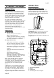
i-on40 1. Introduction The i-on40 is the control unit for a hybrid wired/wirefree alarm system intended for domestic and light commercial use. The control unit comprises an end station and up to four separate wired keypads. The end station has an ABS plastic case which contains the radio transceiver, power supply and backup battery. The keypad(s) connect to the end station by standard alarm cable. The keypads allow end users to set and unset the system, and the installer to configure the control unit.
i-on40 2. Before You Begin Preparation Before installation you should carry out a survey of the site. You need to know how many and what kind of detectors will be transmitting to the control unit. You also need to assess where the control unit must be placed in order to receive radio signals from the detectors successfully. Guided Tour Opening the End Station Case To gain access to the interior of the end station undo the two screws at the top of the case.
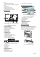
i-on40 5. Printed circuit board (PCB). 6. Cable entry holes for detector and keypad wiring. 7. Transformer. 8. Mains connector block. 9. Cable entry hole for mains. 10. Back Tamper switch (if fitted). 10. Siren test output (not used in UK). End Station PCB 4 Keypad Controls and Displays 1 2 3 8 5 1 A 1 2 abc B 4 ghi 5 jkl 3 def 6 mno C 7 pqrs 8 tuv 9 wxyz D * 0 # 7 6 2 15 3 14 13 12 4 5 6 7 8 9 11 10 Figure 3 End Station Printed Circuit Board 1.
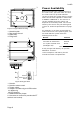
i-on40 3 Before connecting any external devices to the control unit, you must make sure that the control unit can provide sufficient current to power the system during a mains failure for the time required to meet Grade 2 PD6662 or EN50131-1. The amount of current available from the control unit depends on the battery fitted. The current taken by the control unit pcb and keypads is given in Technical Specifications on page 22. 1 2 3 4 Figure 7 Keypad Rear Housing 1. Central keyhole. 2.
i-on40 the back of the end station on a wall. Use No10/M5 countersunk screws at least 36mm long. Figure 9 shows the fixing holes and cable entries. 3. Installation Exposure to Radio Frequency Radiation The radiated output power of this device is below those levels considered safe by European exposure limits. Nevertheless, when fitting the product place it in such a manner as to minimise the potential for human contact during normal operation.
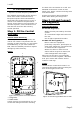
i-on40 Star Connecting Keypads to End Station Daisy Chain Cable Type In general, the control unit requires standard 7/0.2 un-screened four core alarm cable for wiring to keypads. For maximum performance in harsh environments use twisted pair cable with a characteristic impedance of 100-120ohms eg: CAT5 or cable designed for RS485.
i-on40 control unit and 5 in Fig 8 for the keypad). Fitting a jumper to the pins adds a termination to the cable. In a daisy chain configuration terminate each end of the chain (see Fig 11 ). In a star configuration: If there are only two keypads then this is the same as a daisy chain configuration. If required terminate at each keypad. ABCD-ON MENU A 1 2 abc 3 def B 4 ghi 5 jkl 6 mno 7 pqrs 8 tuv 9 wxyz * 0 # The set/unset LEDs shows the setting status of the system.
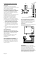
i-on40 Mains Cabling Make sure that the mains supply cable does not run vertically behind the aerials within the end station case. If you wish run mains cable through the side of the case, make sure that they are horizontal for the last metre before entering the case. >1m Step 4.
i-on40 Step 5.
i-on40 Step 6. Fit a Plug-By Communicator If the system has already been installed: The control unit can be connected to a separate communicator or speech dialler (for example, the Scantronic 8400, 8440, 660 or RedCare STU). Figure 20 shows the connections provided by the communications wiring harness. 6. Apply mains power. Com Connector Cable, Part number 485210 4. Re-connect the battery. 5. Fit the case lid. 7. Test communicator operation.
i-on40 Note: Connecting the battery without mains power will not start the system. (See “Programming A Control Unit Before Installation” below if you wish to start the system on battery power.) From this point on, the display operates in the selected language. If you want to change the language later use Installer Menu - System Options - Language.
i-on40 Step 9. Commission the System After installing the control unit you should commission the alarm system as follows: 1. Use the Installer Menu (see Chapter 4) to teach the control unit the identity of its radio detectors and any other peripherals. See the installation instructions supplied with each detector or peripheral. 2. Install detectors and peripherals at their selected locations. 3. Use the Installer Menu – Test (see Chapter 5) option to: a) carry out a walk test of the detectors.
i-on40 4. Programming This section is summary of the Installer Menu on the i-on40. Please see the i-on40 Programming Reference for a more detailed description. Entering the Installer Menu Leaving the Installer Menu If you wish to leave the Installer Menu at any time. X 1. Press until the display shows the words “Leave installer mode?”. Leave installer mode? Y 1. Make sure the system is unset and showing the standby screen (time and date). 2. Press to leave Installer menu.
i-on40 3. Identify the Reset Codes pins on the main PCB (see Figure 3). 4. Short the Reset Codes pins together using a screwdriver or jumper link. (Keep the short on until step 6.) 5. Apply mains power. The control unit loads the factory default access codes: User 1: 1234, Installer: 7890. After a short pause the keypad display shows the time and date. The red LEDs glow to show an alert that the panel lid is open. The system may start a tamper alarm. 6. Remove the short from the Reset Codes pins. 7.
i-on40 Installer Menu 4 SYSTEM OPTIONS 3 SETTING OPTIONS2 Full Set Wired Zone type Name User Access Exit Mode PA keys active Part Set B Quick Set Name Quick Omit Exit Mode User code reqd Part Set Alarm Response User reset Part Set Final Exit Zone alarms7 Zone tampers Part Set Entry Route System tampers Part C, D (See Part Set B) DD243 Exit time Confirmation Entry time Confirmation time Strobe on Set After Entry Strobe on Unset Entry Keypad Lock 3 PARTITIONS1 Sounder on Partition 1...
i-on40 Zone Types & Attributes (Hint: You can select a zone type quickly by keying the number shown in brackets after the type’s name, for example:“05” to select Alarm Abort, “02” to select Panic Alarm, “11” to select External PSU A/C Fail. The number does not appear on the keypad display.) Not Used (00) The alarm system will not respond when an event triggers this detector. Panic Alarm (01). Operating a device programmed as ‘Panic Alarm’ (PA) will start an audible alarm.
i-on40 Notes: 1. The keyswitch zone types are intended for use on zones that connect to an access control keypad, electronic key or other type of hardwired device used to set or unset the system. 2. When the user operates the keyswitch while the system is unset then the control unit starts the programmed exit mode. 3. When the user operates the keyswitch while the system is set then the control unit unsets the system immediately. 4. The user cannot reset the system from a Keyswitch zone. 5.
i-on40 control unit also lights the red LEDs around the navigation key on the keypad to alert the user. You can apply the soak test attribute to Normal Alarm, Entry Route and Tamper zone types. Double Knock Zones programmed with this attribute will cause an alarm only if the zone is EITHER triggered, restored and triggered again within a five minute period, OR if the zone remains active for 10 seconds. You can apply the Double Knock attribute to the Normal Alarm and Entry Route zone types.
i-on40 Type: Active when: RF Supervision (09) There is a supervision failure on any radio zone. The output remains active until all supervision failures are reset. RF Jamming (10) The control unit detects jamming. The output remains on until all jamming disappears. Tamper (16) The control unit detects tamper on any device; deactivates when tamper is reset. RF Fault (11) There are any of the following faults: RF Low Battery, RF supervision, RF jamming.
i-on40 Type: Active when: Type: Active when: operate if the exit mode is silent set or instant set. Part Set B (35) Setting Part Set B. Deactivated on unsetting Part Set B. (Available only in a Part Setting system) Part Set C (36) Setting Part Set C. Deactivated on unsetting Part Set C. (Available only in a Part Setting system) Part Set D (37) Setting Part Set D. Deactivated on unsetting Part Set D. (Available only in a Part Setting system) Set Fail (38) A set command fails.
i-on40 Exit Modes When choosing an exit mode for a partition or a part set, the available options are: Final Door Set Use this option to complete setting the system by closing a door fitted with a Final Exit zone detector. Note that the exit time is infinite in this option. The system allows a seven second settling time after closing a final door. Note: Do not try to make a PIR zone act as a Final Exit. Radio PIR detectors have a “lock out” period after each activation in order to conserve battery power.
i-on40 8. Technical Specification General Product name Product Description Manufacturer Environmental Operating temperature Humidity i-on40. 40 zone hybrid endstation with remote keypads. Cooper Security Ltd. Class II. Tested -10 to +55°C. Case material 0 to 75% RH, noncondensing. ABS LG-AF342. Dimensions: End station Keypad 384 x 245 x 94, mm HxWxD.
i-on40 Monitoring includes Mains fail, battery low voltage, battery failure. Electromagnetic Compatibility Immunity Emissions Conforms to EN50130-4. Conforms to EN61000-6-3. Outputs O/P 1 - 2 O/P 3 - 4 O/P 5 - 16 LS (loudspeaker) Voltage free, single pole relay contacts rated 24VDC @ 1A. Open collector transistor, +12VDC when inactive, 0V when active. 500mA max. Open collector transistor +12VDC when inactive, 0V when active, 50mA max.
i-on40 Compatible Equipment 703rEUR-00 Multi-function transmitter 770rEUR-00 706rEUR-00 Two button PA/tilt switch transmitter Wireless Accessory Module 771rEUR-00 Info Module 710rEUR-00 Two button PA 08844EUR-00 GPRS module 713rEUR-00 Pet tolerant PIR 08750EUR-00 Ethernet module 714rEUR-00 PIR Transmitter (Small case) 9040UK-00 Speaker boxed i-fb01 Four button remote control i-kp01 Keypad i-rc01 Relay Card 720rEUR-00 Smoke Detector Transmitter 726rEUR-50 Long range hand held PA