CT-Interface & IRIS Touch 600 Range Installation Manual Coopers I-ON Panel Range Version 2.
Table of Contents 1 2 3 System Overview ...................................................................................... 3 IRIS Touch 640 PCB Layout ........................................................................ 3 Connections for Coopers I-ON Panel & IRIS Touch..................................... 4 3.1 Power down the Coopers I-ON panel ................................................. 4 3.2 Locate the Coopers I-ON Main PCB as shown below .......................... 4 3.
1 System Overview The Chiron IRIS Touch range of communicators offers a way of transmitting alarm signals to an monitoring centre over an Ethernet (IP) path, GPRS path. There are two parts to the system: 1. 2. A communication device that connects to the alarm panel. A receiver located within the monitoring centre.
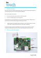
3 Connections for Coopers I-ON Panel & IRIS Touch Please follow the following steps to install and configure the communicator. 3.1 Power down the Coopers I-ON panel 3.2 Locate the Coopers I-ON Main PCB as shown below 3.
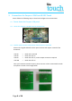
3.4 Plug on the CT-Interface board as show in the image 3.5 Plug the IRIS Touch onto the CT-Interface board For panel versions where you have removed the break outs, you can fix the IRIS Touch to a space within the panel enclosure using the sticky feet. If you have not removed the break out, then remove the sticky feet from the IRIS Touch and plug onto the CT-Interface using the standoffs.
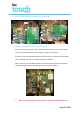
3.6 Connect the Ethernet cable (Ethernet / IP connections) [2] Ethernet cable supplied in the box or any standard Cat5 Ethernet cable. 3.7 Install the antenna (GPRS / GSM connection) [3] Connect the standard T-Bar supplied in the box or a High Gain GPRS antenna with SMA connector to improve the signal coverage (see section 3.11, for GSM network scan). Do not fix the antenna in place until you have performed the Run Network Scan, as detailed in section 3.11.4, to confirm best location. 3.
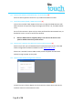
3.10 Once you have connected go to the Remote Touch Screen Tab 3.11 Perform GPRS Network scan (IRIS Touch 640 only) Note: The GSM SIM card should not be installed at this point 1. Select “Installers Menu” and enter the default installer code “111111” and press “OK”. 2. The following screen should now be shown. 3. Note: If not using GPRS as a communication path then please jump to line 10 Select “Run Network Scan” to perform a GPRS network scan for all providers seen from site.
It is recommended that you try the antenna in a number of locations around the IRIS Touch installation, to find the best signal strength for the chosen provider. 4. Fix the antenna in position. 5. Now down power the IRIS dialler. Remove the USB connection 6. Fit the SIM card provided (when GPRS required). Fit the SIM card [5]. 7. Power up the IRIS dialler. Reconnect the USB and connect via the IRIS Dialler Configuration software. 3.
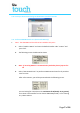
2. Follow the next set of screen to configure up the IRIS Touch Emulation mode Press Settings Press Serial Port RS232 Press Panel Interface Press Emulation Mode Once you have selected the RS232 Cooper i-on option the IRIS Touch Dialler will reboot and you will lose connection. Close down the IRIS dialler configuration connection. 3.
3.14 I-ON Panel Configurations Now configure the panel using the guide below and with the correct information supplied for the site installations.
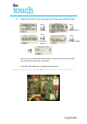
IRIS Touch Configuration & Testing Reconnect the IRIS Dialler Configuration and select and connect, and then continue on the welcome screen. 1. For IRIS Touch 640 only if using a IRIS Touch 620 go to step 2: On the communications page please enter the GSM/GPRS Information for the SIM card provider you are using. USER ID Password Access Point Name (APN) 2. Current default APN’s for UK SIM providers: Vodafone = internet O2 = mobile.o2.co.uk Orange = orangeinternet T-Mobile = general.t-mobile.
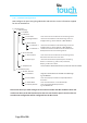
3. Select “Installers Menu” and enter the default installer code “111111” and press “OK”. Note: On the IRIS Touch welcome screen you have some letters and GSM signal Stength shown on the top line, these are indications of the following: E S Poll Ѱ = Ethernet Synchronisation. = Serial communication (RS232). = Communication (polling) to the monitoring Centre. = Shows you have GSM registration and Signal Strength. 8. Select the “Test” option from the Installation Menu. 9.
11. The IRIS Touch will now perform tests over the Ethernet path to confirm polling and alarm are being received by the monitoring centre. Press Continue If you receive a failed message you will be indicated on the screen some reasons for this, please contact Chiron Technical Support if further assistance is needed. Note: If not using GPRS as a communication path then please jump to line 12 12. The IRIS Touch will now perform a test poll and alarm over the GPRS network.
4 Communication trouble reporting The IRIS Touch 600 range simulates the Coopers 8750 Ethernet module, but allows for dual path communication and monitoring (Ethernet & GPRS). Due to the current interface implemented to the Coopers I-ON panel, when the IRIS Touch has communications faults the following indication is report via the panel keypad. Symptoms Panel Status Monitoring Centre Alarm.
5 Appendix B – Specification Ethernet Interface 10Mbps and 100Mbps (10/100BaseT) with auto-negotiation UTP with standard RJ45 socket for CAT-5 cabling Dynamic IP addressing (DHCP) or fixed GSM/GPRS Interface Dual band GSM 900 MHz and DCS 1800 MHz SMA socket for antenna connection IP TCP ports (outbound): 51292 (diagnostics), 52737 (polling), 53165 (alarms), 10001 (Upload/Download).
The future of security, secured IP by security professionals, for the professional security industry Telephone: +44 (0)118 988 0228 E: sales@chironsc.com www.chironsc.com Chiron Security Communications Ltd, Wyvols Court, Swallowfield, Reading, Berkshire, RG7 1WY UK The information contained is supplied without liability for any errors or omissions. No part may be reproduced or used except as authorised by contract or other written permission.