© Cooper Security Ltd. 2011 IN NO EVENT WILL COOPER BE LIABLE FOR ANY SPECIAL, CONSEQUENTIAL , OR INDIRECT LOSS OR DAMAGE, INCIDENTAL DAMAGES, STATUTORY DAMAGES, EXEMPLARY DAMAGES, LOSS OF PROFITS, LOSS OF REVENUE, LOSS OF ANTICIPATED SAVINGS, LOSS OF BUSINESS OR OPPORTUNTIY, LOSS OF GOODWILL OR INJURY TO REPUTATION, LIQUIDATED DAMAGES OR LOSS OF USE, EVEN IF INFORMED OF THE POSSIBILITY OF SUCH DAMAGES.
CONTENTS 1. Introduction ..................................... 1 Communications .................................. 1 Level Setting or Partitioned System ........ 1 Installer Programming Interface ............. 2 About this Guide .................................. 2 2. Before You Begin .............................. 2 Preparation ......................................... 2 Siting the Control Unit and Wired Zone Expanders........................................ 2 Siting Keypads ...............................
i-on30EX This page is intentionally blank.
i-on30EX ID. This module also allows remote maintenance. 1. Introduction The i-on30EX is a control unit for a hybrid wired/wirefree alarm system intended for commercial or large domestic use. The control unit comprises a steel case containing the control unit pcb (printed circuit board), power supply and space for a 7Ah backup battery. The control unit pcb provides terminals for a single bus. The bus allows you to connect up to 10 peripheral devices using standard four wire alarm cable.
i-on30EX Installer Programming Interface Once fitted and powered up, you can program the control unit through any compatible keypad connected to the bus cable. The Installer Menu allows you to specify all the operating parameters for an individual installation. If you wish, you can also connect a PC or laptop to the USB port on the control unit pcb and use Cooper Security‟s Downloader software to program the control unit. Note: Some programming options can make the installation non-compliant with EN50131.
i-on30EX Do NOT site the unit: In the entry or exit zones, or outside the area covered by the alarm system. Close to or on large metal structures. Closer than one metre to mains wiring, metal water or gas pipes, or other metal surfaces. Lower than two metres from the floor (ideally). Inside metal enclosures. Next to electronic equipment, particularly computers, photocopiers or other radio equipment, CAT 5 data lines or industrial mains equipment.
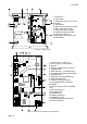
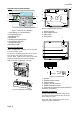
i-on30EX 1. Case back. 2. Fixing holes. 3. Cable entry holes for zone and bus wiring. 4. Transformer. 5. Mains fuse and connector block. 6. Mains cable anchor point. 7. Cable entry hole for mains. 8. Printed circuit board (PCB). 9. Cable entry holes for loudspeakers, siren/strobes and communicators Figure 1 Control Unit 1. Connectors for system bus. 2. Zone-, output-, and Aux power connectors. 3. Plug by communicator connectors. 4. Tamper switch. 5. ADSL filter pins. (i-on30EXD only.) 6.
i-on30EX 1. Built-in communicator telephone line connector. (i-on30EXD only.) 2. Siren and strobe. 3. Loudspeaker. 4. Bus cable connector. 5. Output (transistorised). 6. Aux power. 7. Wired zone connectors.
i-on30EX 3 Keypad Controls and Displays 1 1 2 3 2 8 4 5 7 6 Figure 4 Controls and Displays 1. LCD display (2 x 20 characters). 2. Programming keys. 3. Navigation keys 4. Alert LEDs 5. Setting and unsetting keys. 6. Panic Alarm (PA) keys. 7. Number/text keys. 8. Set/Unset LEDs. 3 4 Figure 6 Keypad Rear Housing 1. Central keyhole. 2. Rear tamper shroud. 3. Cable entry. 4. Fixing holes. Opening the Keypad 2 Note: For EN50131-3:2009, 8.7 the keypad is a type B ACE, fixed.
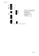
i-on30EX 1 5 1 13 7 8 1 1 6 7 1 9 10 10 12 11 2 2 3 1. Cable entry. 2. Fixing holes. 3. Addressing button. 4. Bus cable connector. 5. Central keyhole. 6. Outputs. 7. Aux power. 8. Lid tamper. 9. Bus address display. 10. Zone connectors. 11. Sounder. 12. Bus termination jumper. 13. Engineering keypad connector 4 Figure 8 Wired Expander 1. Cable entry. 2. Fixing holes. 3. Addressing button. 4. Bus cable connector. 5. Central keyhole. 6. Bus address display. 7. Loudspeaker terminals. 8. Sounder. 9.
i-on30EX Power Availability Before connecting any external devices to the control unit, you must make sure that the control unit can provide sufficient current to power the system during a mains failure for the time required to meet the appropriate standard. EN51031-1 Grade 2 and PD6662 Grade 2 both require 12 hours standby time. Note: When calculating the average load during the standby time period you must allow for at least two periods in alarm.
i-on30EX Cable Configuration and Length You can connect up to 10 devices to the control unit bus. You may connect the devices either in daisy chain (serially), or in star (parallel) configuration at the control unit connector. Figure 10 Bus Wiring Configurations For star configurations the cable length from control unit to the most distant bus device should be kept short, and should not exceed 100m. There should be no more than four arms in the star.
i-on30EX Table 1. Voltage Drop Current Drawn 60mA 80mA 100mA 120mA 140mA 160mA 180mA 200mA 220mA 240mA 260mA 280mA 300mA 320mA 340mA 360mA 380mA 400mA Cable Length (Standard 7/0.2 alarm cable) 10m 0.10V 0.13V 0.16V 0.19V 0.22V 0.26V 0.29V 0.32V 0.35V 0.38V 0.42V 0.45V 0.48V 0.51V 0.54V 0.58V 0.61V 0.64V 20m 0.19V 0.26V 0.32V 0.38V 0.45V 0.51V 0.58V 0.64V 0.70V 0.79V 0.83V 0.90V 0.96V 1.02V 1.09V 1.15V 1.22V 1.28V 30m 0.29V 0.38V 0.48V 0.58V 0.67V 0.77V 0.86V 0.96V 1.06V 1.15V 1.25V 1.34V 1.44V 1.55V 1.
i-on30EX 3. Installation Where the cable run from the control unit will be longer than 100m (see Cable Configuration and Length). Note: The installation steps listed below assume that you have already decided on the required number and location for all keypads, expanders and power supplies. Note: Do not site two or more keypads closer than one metre together, otherwise their prox readers will interfere and be unable to read tags.
i-on30EX The jumpers have the following functions: ABCD-ON ABCD-ON The set/unset LEDs are disabled. ABCD-ON ABCD-ON ABCD-ON ON BLABCD-ON The set/unset LEDs shows the setting ABCD-ON BRIGHT status of ON the system. (Full set is the left BL BRIGHT hand LED.) ABCD-ON ABCD-ON ON BL ON BL BRIGHT BRIGHT ON BL BRIGHT ABCD-ON The key backlights are disabled. They ON BL glow will briefly for five seconds when a ON ON BL BRIGHT BL user presses a key.
i-on30EX Each loudspeaker draws up to 280mA in operation. if there is more than one expander loudspeaker then the bus may not be able to supply sufficient current during an alarm. different on the expander compared to the control unit. Step 5. Connect Control Unit to Mains WARNING: ENSURE THAT THE MAINS SUPPLY IS DISCONNECTED AND ISOLATED BEFORE MAKING ANY MAINS CONNECTIONS.
i-on30EX When programming select the FSL resistor values for the control unit in Installer Menu System Options - Wired Zone Type. To select the resistor values for a wired expander use Installer Menu – Detectors Devices – Wired Expanders - Edit Expander. If you wish to connect two or more detectors to a FSL zone, Figure 20 shows the connections required. Figure 20 Wiring Two Detectors per Zone FSL.
i-on30EX program the control unit zones‟ wiring type as 2-wire FSL, with 2k2/4k7 resistors. See i-on Range Engineering Guide part number 12098019 for more details. Step 7. Connect Wired Outputs Wired External Sounders (Optional) Wired external sounders differ in their methods of connection. Figure 23 shows an example of a general method of using the outputs to connect a wired sounder. Note: If you do not wish to connect a wired external sounder then make sure you link TR to 0V.
i-on30EX Figure 25 shows a general method of using the outputs on a wired expander to connect a wired external sounder. Connect the tamper wiring to an unused zone connection on the expander. For 4wire CC zones use the alarm contacts only and link the tamper contacts together with a short length of wire. For FSL wiring, connect a 2k2 resistor in series with the link from –TR on the external sounder to the left hand terminal of the zone connector see Figure 27.
i-on30EX Step 8. Connect the Internal Communicator (i-on30EXD only) The i-on30EXD version of the control unit has an internal communicator on its main PCB. This is an auto-dialling modem. If necessary, a standalone communication device can be connected through a wiring harness to interface pins on the main PCB (this is known as a plug-by communicator, see page 19).
i-on30EX Safety Notice Figure 28 identifies connectors for Safety Extra-Low Voltage (SELV) and Telecommunications Network Voltage (TNV) circuits on the control unit's main PCB. These terms are used in accordance with the definitions in Safety Standard EN60 950. The Installer must ensure that TNV terminals are connected only to other circuits designated as TNV circuits (for example, the PTSN) and that SELV terminals are connected only to other circuits designated as SELV circuits.
i-on30EX Figure 31 Plug-By Communicator Wiring Note: Comms O/P4 will be active when the system is unset. This is normal. To fit a communicator, follow the instructions below. Caution: Follow the instructions in the order shown, or you may damage the control unit and/or communicator. Figure 30 Fitting the ADSL01 Filter. Note: If you remove the ADSL01 filter then re-fit the jumpers to the outermost pairs of pins. If you fail to re-fit the jumpers the internal communicator will not connect to the phone line.
i-on30EX Line Monitoring for a Dual-Path Communicator If a standalone dual-path (landline and mobile) communication device, such as a RedCARE STU, is connected to the plug-by connector, you need to do the following to obtain correct line fault reporting that complies with BSIA Form No.175, April 2005 (this is not necessary if you are using a plug-on module): 1. Reprogram one of the plug by outputs to type “ATS Test” and wire that output to the ATS Test input of the communicator. 2.
i-on30EX 4. Press or to show other countries, for example 5. Press to select the country you want. The display shows: 6. Press A or B to select either a Partitioned system or a Part Setting system. 7. Press or to show the range of zone wiring types available, for example: 8. Press to select the wiring type you intend to use for the wired zones.
i-on30EX Leaving the Installer Menu If you wish to leave the Installer Menu at any time. 1. Press until the display shows the words:. 2. Press to leave Installer menu. (Press if you do not want to leave the menu.
i-on30EX As you start to key in the code the display shows: When you key in the last digit of the Installer access code the display shows: Note: You will see this screen the first time you enter the Installer menu on a new control unit, or if you have restored Factory Defaults. 3. Key in the default user code (see Note below). The default user access code is “1234”. The display shows: 4.
i-on30EX 3. Press A or B to select the desired mode. The display shows: 4. Press or to display the desired wiring type on the bottom line of the display and then press to select it. The system loads all defaults except for Access Codes and the Log. The display briefly shows: Followed by: 5.
i-on30EX Installer Menu 1 DETECTORS/ DEVICES Detectors Add/Del Detectors Program Zones Address Bus Device Wired Expanders Address Bus Device Edit Expander Delete Expander Enable Expander Replace Expander Radio Expanders Address Bus Device Edit Expander Delete Expander Enable Expander Replace Expander Wired Keypads Address Bus Device Edit Keypad Delete Keypad Enable Keypad Replace Keypad Radio Keypads Add/Del Radio Keypad Edit Keypads External Sirens Add/Delete Ext.
i-on30EX 1 Appears only in a Partitioned system (or when zones have a type other than “Not Used”). Appears only in a Level Setting system. 3 Appears only when Report Type=Fast Format 4 Appears when Report Type=CID or SIA 5 Options visible depend on communications module fitted, or if using i-on30EXD. 6 Appears when zone is given a type other than “Not Used”. 7 Appears only when System Options – DD243 – Confirmation is “off”. 8 Appears only when device learned in.
i-on30EX 5. Technical Specification 4. Maintenance The control unit should be inspected once per year. At each inspection: Check the control unit for obvious signs of damage to the case or its lid. General Check the keypads for obvious signs of damage. Product name Product Description Manufacturer Environmental Operating temperature Humidity Test the action of all buttons on all keypads. Case material 0 to 93% RH, noncondensing. Steel. Dimensions: Control unit Keypad 240 x 250 x 87, mm HxWxD.
i-on30EX Log capacity Up to 350 events: 250 mandatory events, 100 nonmandatory. Stored in EEPROM memory, available for at least 10 years without power. Internal Clock ±10 minutes over one year (depending on the accuracy of the mains supply frequency). User Codes 50 (plus installer code) Remote controls 50 (one per user) Panic Alarms 50 (one per user) Proximity tags 50 (one per user) Notes: 1. Wired keypads, wired zone expanders, and radio zone expanders are all bus devices.
i-on30EX 12V Bell output voltage range Max p-to-p ripple voltage: Standby Battery: „Low battery‟ fault at: Aux power output fault at: Deep discharge protection at: Serviceable components: Standby time: 10±0.5V to 13.8V Radio 0.5V 12V, 7Ah sealed lead acid (not supplied). < 12V < 9V 10±0.5V Mains fuse: 250mA (T) See “Power Availability” on page 8. Electromagnetic Compatibility Immunity Emissions Conforms to EN50130-4. Conforms to EN61000-6-3.
i-on30EX Compatible Equipment 706rEUR-00 Two button PA/tilt switch transmitter 710rEUR-00 Two button PA 713rEUR-00 Pet tolerant PIR 714rEUR-00 PIR Transmitter (Small case) 720rEUR-00 Smoke Detector Transmitter 726rEUR-50 Long range hand held PA 726rEUR-60 Short range hand held PA 734rEUR-00/01 CC/FSL Door Contact Transmitter (white) 734rEUR-05/06 CC/FSL Door Contact Transmitter (brown) 738rEUR-00/04 Spyder shock sensor (white/brown) 739rEUR-25 Sentrol glass break detector (no tamper)
i-on30EX NOTES: Page 31
i-on30EX www.coopersecurity.co.uk Product Support (UK) Tel: +44 (0) 1594 541979. Available between: 08: 30 to 17:00 Monday to Friday. Product Support Fax: (01594) 545401 email: techsupport@coopersecurity.co.