Security System Programming Reference
© Cooper Security Ltd. 2010 Every effort has been made to ensure that the contents of this book are correct. However, neither the authors nor Cooper Security Limited accept any liability for loss or damage caused or alleged to be caused directly or indirectly by this book. The contents of this book are subject to change without notice. Printed and published in the U.K. This manual applies to software used in the i-on40 control unit with version 2.02 software.
i-on40 Contents Introduction .......................................................................1 About this Guide ............................................................... 1 System Overview .............................................................. 1 Part Setting or Partitioned System......................................................1 Communications ..............................................................................2 Entering and Leaving Installer Menu........................
i-on40 Mains Fail Delay ............................................................................ 59 Communications.............................................................. 60 ARC Reporting............................................................................... 61 Speech Dialler ............................................................................... 68 SMS............................................................................................. 73 Line Fail Response .............
i-on40 Introduction About this Guide This guide contains a detailed description of programming an i-on40 system using the Installer Menu. To install, connect and start up an i-on40 control unit please read ion40 Installation Guide. If you need to add or administer users (and their remote controls, PA buttons and prox tags) then you must enter the User Menu. This is described in detail in the i-on40 Administrator’s Guide. Note: Setting the time and date is also an administrative user function.
Introduction i-on40 Part Setting. In a Part Setting System the i-on40 can set in one of four ways: either Full set or three varieties of Part Set. In Full Set the control unit pays attention to all detectors. In each of the three Part Sets, the control unit ignores all detectors that do not have the appropriate Part Set attribute (see page 16 ). Partitioned System. In a Partitioned system the i-on40 provides the equivalent of four, smaller, independent alarm systems.
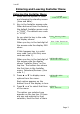
i-on40 Entering and Leaving Installer Menu Entering the Installer Menu 1. Make sure the system is unset and showing the standby screen (time and date). 2. Key in the Installer access code. When delivered from the factory the default Installer access code is “7890”. The default user code is “1234”.
Entering and Leaving Installer Menu i-on40 appears on the bottom line. Press u or n to display the other sub-options. Note: 1. After you initially gain access to the Installer Menu, you may leave and re-enter using the Installer access code by itself for up to 30 minutes after you last exited the Installer Menu. After that time you will need to enter a valid user access code to complete your entry into the Installer Menu (note that you cannot use a Set Only user code).
i-on40 Entering and Leaving Installer Menu Press X to return to the Installer Menu. You must rectify the fault (or delete the device from the system) before you can leave the Installer Menu. Important! Saving Changes to the Installer Menu When you make changes to the Installer Menu the control unit holds those changes in temporary memory until you leave the Installer Menu. As you leave the Installer Menu the control unit writes those changes into a permanent store.
Entering and Leaving Installer Menu 6. i-on40 Remove the short from the Reset pins. 7. 8. Reconnect the battery. Close the control unit lid (to restore the tamper switch). 9. Key in the Master User code 1234 to silence the sirens. Press Y twice (if necessary) to acknowledge any alerts. To force the control unit to check the battery: 10. Enter installer menu and then leave it again. The navigation key LEDs should now glow green.
i-on40 Installer Mode Programming This section is a reference for all the options provided in the Installer Menu. Apart from “Naming Things/Editing Text” below all the section headings appear in the same order as the options appear in the Installer Menu on a keypad. Editing Text In the i-on40 zones, setting levels, partitions, keypads, outputs and users can all be named. Also, account numbers for Downloader can take letters as well as numbers.
Installer Mode Programming i-on40 one character and you can insert a new character in the empty space. To move the cursor left or right press u or n respectively. To delete characters press <. Note: If you wish to leave a name or text unchanged then press X. The display leaves the name change screen and restores the name to its previous value. Press Y when you have finished entering text.
i-on40 1. Installer Mode Programming Use the u or n keys to highlight a free zone and press > or Y. The display shows an “*” next to zones where the control unit has already learned detectors. 2. Activate the detector’s tamper. The keypad sounds a double “beep” when the control unit successfully learns the detector. The display shows a message to confirm that you have learned the detector to the selected zone, together with the current signal strength of the transmitter. 3.
Installer Mode Programming i-on40 1. Use the u or n keys to highlight a zone you wish to delete (the display shows an “*” next to zones that have detectors) and press >. 2. You have the choice of deleting the detector ID or of defaulting the zone. Press u or n to see each of these choices. If you select “Delete Detector ID” then the control unit “forgets” the ID of the detector, but leaves any zone programming in place.
i-on40 2. Installer Mode Programming When you have found the zone you wish to edit press > or Y. The bottom line of the display shows “Name”. 3. Press u or n to see the Type, Attributes or Partition options for that zone. Press > or Y to select the option you wish to change.
Installer Mode Programming i-on40 Reporting option (see page 61). PA alarms operate whether the system is set or unset. Fire Alarm (02). Smoke or heat detectors connected to Fire Alarm zones cause the sirens to give a pulsing fire signal. Fire alarms operate whether the system is set or unset, and will always trigger communications, if a communications module is fitted and enabled. Normal Alarm (03). A zone programmed as ‘Normal Alarm’ will start an alarm when the system is set. 24 Hour Alarm (04).
i-on40 Installer Mode Programming full alarm. If a technical alarm zone is activated (and the control unit correctly programmed, see page 60 ) then the control unit starts communication and logs the event. If the technical alarm occurs while the system is set, then system makes no audible alarm. When a user unsets the system the keypad shows an alert.
Installer Mode Programming i-on40 to set or unset the system. 2. When the user operates the keyswitch while the system is unset then the control unit starts the programmed exit mode. 3. When the user operates the keyswitch while the system is set then the control unit unsets the system immediately. 4. The user cannot reset the system from a Keyswitch zone. 5. Do not assign more than one Latched Key Switch zone to a partition.
i-on40 Installer Mode Programming If the alarm system is set then the control unit logs the event, starts any programmed communication, but does not start an alarm. External PSU Low Volts (13). Use this zone type to monitor the Low Voltage output of an external power supply unit. If a power supply triggers a zone with this type then the control unit activates any output programmed as “Low Volts” and causes an alert that displays “External Low Volts” on the keypad.
Installer Mode Programming i-on40 2. Scroll through the list of partitions for that zone. Press the > or < keys to change the status of the zone. “Yes” means the zone is allocated to that partition. 3. Press Y to save your changes and return to the list of zones. When delivered from the factory, or if you restore the control unit to factory settings, then all zones belong to partition 1. Zone Attributes Note: This menu does not appear if a zone has the type “Not Used”.
i-on40 Installer Mode Programming Alarm, Entry Route and Tamper zone types. During setting the keypad displays a brief message to inform the user that one or more zones are in soak test. Double Knock Zones programmed with this attribute will cause an alarm only if the zone is EITHER triggered, restored and triggered again within a five minute period, OR if the zone remains active for 10 seconds. You can apply the Double Knock attribute to the Normal Alarm and Entry Route zone types.
Installer Mode Programming i-on40 them and pauses the setting procedure. The user can acknowledge the alert by pressing Y and continue setting. You must enable this feature in the System Options – User Access – Quick Omit menu, see page 50. Force Set Omit When this attribute is set to Yes a user with a remote control can set the system while the zone is open (active). (You must enable this feature in the System Options – Force Set menu. See page 57.
i-on40 Installer Mode Programming Assigning keypads to Partitions The i-on40 allows you to assign keypads to any of the partitions. Once you have assigned a keypad to a partition then that keypad will display messages and give tones for the assigned partition(s). However, any user can use any keypad. While they are using a keypad the display shows information from partitions assigned to the user, not to the keypad. To assign a keypad to a partition: 1. Select Detectors/Devices – Wired Keypad.
Installer Mode Programming i-on40 might part set partitions 1 and 2, but on keypad 2 it could be programmed to full set partition 3. In addition, each of the A, B, C or D keys can have a name. The keypad displays this name while the system is setting after the user presses that key. To name and assign the action of a quick set key: 1. Select Detectors/Devices - Wired Keypads. The bottom line of the display shows the first in a list of the wired keypads. 2.
i-on40 9. Installer Mode Programming Repeast steps 2 and 3 to set the action for all the partitions. 10. Press Y to save the listed actions for that key. Radio Keypads The Radio Keypad is a transmitter that users can employ to set and unset the system remotely. The Radio Keypad is a transmitter only, and does not display any system information. The LEDs on the Radio Keypad glow to show that it is transmitting a signal.
Installer Mode Programming i-on40 Deleting an Radio Keypad To remove a Radio Keypad from the system: 1. Select Detectors/Devices – Radio Keypad – ADD/DEL Radio Keypad. The bottom line of the display shows “Radio Keypad 1”. This is the first in a list of four available memory slots for Radio Keypads. If a memory slot is occupied then the beginning of the line shows a “*” icon. 2. Press u or n to scroll to the Radio Keypad that you wish to delete. Then press Y.
i-on40 1. Installer Mode Programming Select Detectors/Devices – Radio Keypad. The bottom line of the display shows the first in a list of “memory slots” for the radio keypads. If a memory slot is occupied by a radio keypad then the bottom line of the display shows a “*” at the beginning of the line. 2. Press u or n to select the radio keypad you wish to assign to a partition, then press >. The bottom line shows the first partition.
Installer Mode Programming 1. i-on40 Select Detectors/Devices – External Siren – Add/Del Ext Siren. The display shows four possible “memory slots” for external sirens. A slot already allocated to a siren shows a “*” at the beginning of its line. 2. Select an empty memory slot. The display shows a message asking you to operate the siren’s tamper. 3. Operate the siren’s tamper. The control unit learns the siren’s identity and gives a double beep.
i-on40 1. Installer Mode Programming Select Detectors/Devices – External Siren – Add/Del Ext Siren. The display shows four possible “memory slots” for external sirens. A slot already allocated to a siren shows a “*” at the beginning of its line. 2. Select the siren you want to delete. The display shows the message “Delete Ext Siren”. 3. Press Y to make the control unit “forget” the siren ID learned into that memory slot.
Installer Mode Programming 5. i-on40 Press Y on the i-on40 keypad to confirm that the Info Module has learned the identity of the i-on40. Disabling Info Modules If you physically remove the Info Modules from a system (for example, when a user no longer requires them) then you may wish to stop the control unit trying to update the Info Module’s display. The Detectors/Devices–Info Module menu provides the Updates option for this purpose. To disable updates on an Info Module: 1.
i-on40 Installer Mode Programming When you select Disabled, the control unit stops using the Ready to Set LED the Info Module. 3. Press Y to confirm the change. WAMs The i-on40 can operate up to two 770r WAM modules. Although the WAM provides five different modes, when working with an i-on40 only three of them are relevant. The installer selects the mode when commissioning the WAM hardware. The modes provide the following functions for the i-on40 control unit: Mode 1 Repeater Module.
Installer Mode Programming i-on40 To teach the control unit the WAM’s identity: 1 Select Detectors/Devices – WAM – Add/Del WAM. The bottom line of the display shows the first of two available “memory slots” for learning WAM modules. Each memory slot can hold the identity of a single WAM module. When a slot is occupied with a WAM then the bottom line shows a “*” at the beginning. 2. Press u or n to select the memory slot that you wish to use, followed by Y.
i-on40 Installer Mode Programming Deleting a WAM To remove a WAM from service in the system, then: 1. Select Detectors/Devices – WAM – Add/Del WAM. The bottom line of the display shows the first in a list of the available WAMs. 2. Press u or n to select the WAM you wish to delete then press Y. (When a slot is occupied with a WAM then the bottom line shows a “*” at the beginning.) The display asks you to confirm your choice. 3. Press Y.
Installer Mode Programming 1. i-on40 Select Outputs – Radio Outputs – Add Outputs. The bottom line of the display shows the first in the list of eight available radio outputs. 2. Press u or n to select the radio output that you wish to make the receiver learn and press Y. The keypad displays a reminder: “Is the receiver in learn mode?” 3. Make sure the receiver is powered up. Follow the programming instructions for the receiver to make it learn the control unit into the desired channel. 4.
i-on40 3. Installer Mode Programming Press > to give the output a name. See page 7 for hints on editing names. Press Y when you have finished editing the name. To give a radio output a type: 1. Select Outputs – Radio Outputs – Edit Outputs. The bottom line of the display shows the first of eight available radio outputs. 2. Press u or n to select the radio output that you wish to give a type and press Y. The bottom line of the display shows the word “Name”. 3.
Installer Mode Programming i-on40 The i-on40 also lets you change the polarity of the wired output, to suit the type of equipment that the output must work with. To give a wired output a name: 1. Select Outputs – Wired Outputs. The bottom line of the display shows the first in the list of four available wired outputs. 2. Press u or n to select the wired output that you wish to name and press >. The bottom line of the display shows the word “Name”. 3. Press > to give the output a name.
i-on40 Installer Mode Programming You can remove the output from Partition 1 by pressing < or > to change the “Yes” to a “No”. Press u or n to scroll to other Partitions. Press < or > to assign the output to each Partition as required. Press Y when you have finished assigning outputs to Partitions. 4. Press n to scroll down to the next output. Polarity This option allows you to change the polarity of the wired outputs.
Installer Mode Programming i-on40 type, and change its polarity. Programming plug-by outputs is the same as programming wired outputs, but you must use the Outputs – Plug-by Outputs menu. Note: The activity of the plug-by outputs is affected by the alarm response you select. For example, if you select the alarm response “Siren” for Part Set B, then the control units will not trigger the Plug-by-Outputs if there is an alarm when the system is in part set B.
i-on40 Installer Mode Programming Type: Active when: Open/Close (04) The system is unset. Inactive when the system is set. An alarm in the selected partition has been aborted by the user within the 90s abort period. Deactivates when the alarm is reset. There is a technical alarm. Alarm Abort (05) Technical Alarm (06) Confirmed Alarm (07) RF Low Battery (08) RF Supervision (09) RF Jamming (10) RF Fault (11) There is a confirmed alarm. Deactivates when the system is reset.
Installer Mode Programming Type: Active when: Panel A/C Fail (12) Either Mains power is absent for between 52 and 59 minutes, OR a zone of type “External PSU A/C Fail” has been triggered. The control unit deactivates the output if a user keys in a valid access code after mains power has been restored. Note: If the External PSU A/C Fail zone is activated while the control unit is still receiving mains power then the control unit will activate this output within a few seconds.
i-on40 Installer Mode Programming Type: Active when: Panel Battery Fault (13) The control unit detects a fault with its backup battery, OR a zone of type “External PSU Battery Fault” has been triggered. If the alert was caused by an “External PSU Battery Fault” zone then the control unit deactivates the output when the zone has been restored and a user has acknowledges the fault by entering a valid access code.
Installer Mode Programming Type: External PSU Fault (15) Active when: An external power supply fault signal triggers a Power output fault zone. The control unit deactivates the output when the zone has been restored and a user has acknowledges the fault by entering a valid access code. Tamper (16) The control unit detects tamper on any device; deactivates when tamper is reset. Zone Omit The user Omits a zone (Setting) (17) while setting the system.
i-on40 Installer Mode Programming Type: Active when: ATS Test (20) (This output type appears only for Plug-by outputs.) The line fault input signal goes to 12V. The operation of the Line Fault input and the ATS test output complies with the requirements of BSIA form 175. The control unit starts a full Yes alarm, a panic alarm or a fire alarm (the siren has a distinctive tone during a fire alarm). The control unit deactivates this output at the end of the siren time.
Installer Mode Programming Type: Active when: Entry Exit Follow (23) The entry or exit time starts and deactivates at the end of the entry/exit time, or if the entry/exit time is terminated. The output can be used for a separate entry/exit buzzer. Note that the output does not operate if the exit mode is silent set or instant set. The system is full or part set. The system is set. Inactive when the system is unset or an alarm condition occurs.
i-on40 Type: Installer Mode Programming Active when: Smoke Sensor This output is active (0V) Reset (28) all the time except when a user acknowledges a fire alarm: after which the control unit deactivates the output for three seconds. This output type is designed to be connected to low-voltage smoke detector reset terminals. 24 Hour The control unit starts a 24 Alarm (29) hour alarm. Setting The control unit finishes Complete (30) setting. Active for 10 seconds.
Installer Mode Programming Type: Active when: Part Set D (37) Setting Part Set D. Deactivated on unsetting Part Set D. (Available only in a Part Setting system) A set command fails. Remains active until the user acknowledges the set fail. A specified zone has been triggered. If you select this type for a zone then the display shows an extra “Follow” option for the output. Use this option to select the zone you wish the output to follow. (You can follow a “not used” zone.
i-on40 Installer Mode Programming Type: Active when: User Defined (41) The user switches the output on or off from the keypad, or a remote control. Assign this output type to any outputs that you want the user to control. Note: Cooper Security recommend that you DO NOT assign this output type to a plug-by-output.
Installer Mode Programming i-on40 menus, the table shows the page number where the description of each option can be found. 3 SETTING OPTIONS PAGE 3 PARTITIONS Full Set Partition 1...
i-on40 Installer Mode Programming Partition a name. The control unit displays this name to the user during setting. Exit Mode The exit modes available are: Timed Set Use this option to make the system set after a delay. Use the Exit Time menu (see page 46) to choose the delay. Final Door Use this option to complete setting the Set system by closing a door fitted with a Final Exit zone detector. Note that the exit time is infinite in this option.
Installer Mode Programming i-on40 menu but does not give any exit tones. When the system sets the keypad gives a double beep confirmation tone. The keypad(s) give a double beep confirmation tone at the end of all setting modes. Settle Time This option allows you to define a time delay to allow detectors to settle before the system sets. This may be needed if detectors are being set off by air movements caused by the final door being closed.
i-on40 Installer Mode Programming activate any output programmed as Strobe, plus the strobe on any 760ES wireless siren. The outputs/strobes are active for three seconds after the system unsets. Strobe On Unset applies to Full Set and all the Part Sets. Alarm Response You can select one of the following: Internal: Keypads and loudspeakers Siren Keypads, loudspeakers and siren Siren + Comms Keypads, loudspeakers, siren and communication.
Installer Mode Programming i-on40 Routes during part set. In a Partitioned system, all Entry Route zones, belonging to the partition, with the Part Set attribute will continue to act as Entry Routes during part set. Final Exit In a Part Setting System, any Entry Route zones with the Part Set B, C or D attributes will act as Final Exit zones during part set. In a Partitioned system, any Entry Route zones, belonging to the partition, with the part set attribute will act as Final Exit zones during part set.
i-on40 Installer Mode Programming This option lets you change the zone wiring type. Note that there are several options of resistor values for FSL: the keypad display shows the alarm contact resistor/end of line resistor values for each option. If you select “4 Wire CC” then the control panel provides eight wired zones, numbered zone 01 to zone 08. If you select any of the FSL options then the control unit provides 16 wired zones, numbered zone 01 to zone 16.
Installer Mode Programming i-on40 Quick Omit This option allows users to omit a zone that is active (has it’s alarm contacts open) while they are setting the system. The zone must have the Omittable attribute (see page 16). Yes By pressing Y the user can set the system if there are zones with the Omit Allowed attribute active. No The user must go to the Omit Menu to set the system if a zone is active.
i-on40 Installer Mode Programming System Tampers Yes The user can reset the system after an alarm caused by a system tamper, for example the control unit lid opening, or a keypad being opened. No The installer must reset the system after a system tamper alarm. Note: This setting is required for INCERT approval. DD243 (UK Only) Note: This menu is visible only when System Options – Restore Defaults – Country defaults is set to “UK”.
Installer Mode Programming i-on40 Entry Keypad Lock This option determines whether the user can unset the system by entering an access code after opening the entry door. Off: The user can enter an access code at the keypad after the entry door opens (used for DD243:2004 clause 6.4.4). On: The user must unset the system by some means other than the keypad, for example prox tag or remote control (used for DD243:2004 clause 6.4.5).
i-on40 Installer Mode Programming page 50). You may then use the options below: User: The user can reset after a confirmed alarm. Installer: The user cannot reset after a confirmed alarm, the installer must do it. Note: If a user causes an alarm which would require Installer reset then they have 120s to abort the alarm, which they can then reset themselves. Profiles This option loads a set of standard entries for all names, and sets up other options.
Installer Mode Programming i-on40 Web Server you must key into the Username field the same text as you have programmed into the Installer Name field. Installer Code The default Installer access code is 7890. Cooper Security Ltd recommend that you change this code to some other number. To change the Installer access code select System Options-Installer Code. The Installer code allows you to enter the Installer Menu, and carry out an Installer reset.
i-on40 Installer Mode Programming enabled, or the communications outputs wired to an appropriate communicator and correctly programmed). This option controls the associated audible alarm. Audible As well as starting communications the control unit starts PA alarm tones from the keypads and loudspeakers, and activates any siren outputs. Silent The control unit keeps the PA alarm silent: there are no alarm tones from keypads or loudspeakers and any siren outputs remain inactive.
Installer Mode Programming i-on40 programmed Siren Delay before operating the siren. The system then operates the siren for the programmed Siren Time. Note: Siren Delay has no effect if the Alarm Response Mode does not require communications or if a line fault is detected. Siren Time This option changes the length of time that the system operates the siren during an alarm. Note: The durations offered by the display apply to a siren wired directly to the control unit.
i-on40 Installer Mode Programming If a wirefree detector loses contact for more than two hours then the control unit raises an alarm. The options available for this alarm are: Option: Disabled Fault With system SET, the control unit: Does nothing. With system UNSET the control unit: Does nothing. Logs the event (but Displays an Alert and does NOT display any sounds a fault tone and alert or fault tone). logs the event. Jamming The control unit can detect interfering (or "jamming") radio signals.
Installer Mode Programming i-on40 On The user need only press the remote control button once to complete setting the system. Note: The Confirm and On options will also allow a user with a remote control to set the system if a reset is required after an alarm. If any user is attempting to reset the system from a wired keypad when a remote user tries to set the system, then the control unit will temporarily ignore the remote user.
i-on40 Installer Mode Programming code. This acts as a seed for computing both the reset code and its anti-code. The ARC usually generates the CSID code. To install the CSID code: 1. Call the ARC and obtain the CSID code. 2. Enter the Installer Menu and select System Options – Remote Reset. 3. Key in the CSID code. As you press the final digit the control unit stores the code and displays the System Options menu. Note: To disable this option key in “0000” over the existing code.
Installer Mode Programming i-on40 The values available are 0 to 10 minutes. Note that when the value is set to 0 minutes, mains interruptions of less than 9 seconds will not start an alert. Communications Note: If you have connected a plug-by communicator then use the Outputs - Plug-by Outputs menu to program the communicator. The Communications option in the Installer Menu contains all the options needed to program how the control unit will communicate alarms.
i-on40 Installer Mode Programming Downloading Deals with setting up phone numbers, account numbers for the downloader, and controlling the type of connection you wish to allow. Note: Apart from Downloading and IP Network (Own), the above menu items appear only if the appropriate module is fitted. The control unit is designed to alert the user if it fails to complete a programmed communication. If alarm reporting fails then the keypad displays an alert by lighting the red LEDs around the navigation keys.
Installer Mode Programming i-on40 control unit ends the call and then re-attempts to connect up to a maximum of 15 times. Alternate. The control unit reports to one of the two telephone numbers in the Phone Book. Operation: The control unit dials the first telephone number and attempts to connect to the ARC. If it fails, it will then close down and dial the second telephone number and attempt to connect to the ARC. If received and acknowledged on this attempt, the alarm transmission is complete.
i-on40 Installer Mode Programming 1. You understand basic IP terminology. 2. You have obtained the necessary information from your Internet Service Provider. Unit Name Use this option to store a unique name for the unit. Polling IP Address Key in the IP address of the remote polling engine. If the ARC is not using a polling engine then leave this option blank. ARC IP Address Use this option for the ARC’s main IP addresses.
Installer Mode Programming i-on40 If you selected Fast Format in Report Type then you can select Communications - ARC Reporting - Fast Format Channels to allocate one of the following events to each of eight channels (defaults in brackets): Not used Fire Alarm (default Channel 1) Panic Alarm (default Channel 2) Burglar Alarm (default Channel 3) Open/Close (default Channel 4) Alarm Abort (default Channel 6) Technical Alarm (default Channel 8) Confirmed Alarm (default Channel 7) RF Low Battery RF Supervisio
i-on40 Installer Mode Programming CID/SIA Events (This menu appears only if you select “Contact ID” or any of the SIA versions in Communications - Report Types. See Appendix II for a description of the CID and SIA formats.) To make programming easier, the i-on40 groups CID/SIA telegrams together into Report Groups. Table 3 lists the telegrams included in each report group, and the relevant CID/SIA codes.
Installer Mode Programming i-on40 Omit Zone omit 573 BB RF Supervision Zone supervision fail and restore 381 BZ Radio keypad supervision fail and restore External siren supervision, fail and restore* RF Jamming Jamming fail and restore* RF Battery/PSU Smoke power supply unit fail and restore Panel Battery 344 337 Zone low battery fail and restore 384 Ext Siren low battery fail and restore 338 Control unit low battery and restore 302 Control unit battery missing and restore 311 YM, YR,
i-on40 Installer Mode Programming Burg Comms Rearm (This menu appears only if you select “Fast Format” in Communications - Report Type.) This menu option determines what the control unit does with the “Burg” Fast Format channel 3 at the end of the siren run time. There are two options: Disabled The channel stays active until an Installer or user resets the system. Enabled The system rearms Channel 3 once the siren timer has expired. Once the Channel is rearmed, the system is ready to report any new alarm.
Installer Mode Programming i-on40 Dynamic Test Call In dynamic testing the system makes a test call 24 hours after the last alarm communication. To enable dynamic testing select Communications – ARC Reporting – Dynamic Test Call – Enabled. Static Test Call In static testing the system makes a test call either on: Every day at one particular time of day or On the same day of every week, or On one day every month.
i-on40 Installer Mode Programming microphone and replay them to a pre-programmed telephone number to report an alarm. One message is called the “Home message”, and is always played at the beginning of a report. You should use this message to identify the control unit and it’s location. The other four messages allow you to record some indication of the type of event causing an alarm, for example: “Fire” or “Panic Alarm”. The control unit plays these messages after the home message.
Installer Mode Programming i-on40 control unit (usually by pressing buttons on the telephone key pad). The commands available are: Function Key End this call DTMF ‘5’ Play ‘Home’ and ‘alarm’ message DTMF ‘3’ Clear down DTMF ‘9’ Note that when the called party answers a speech dialler call there could be a six second delay before the control unit starts playing the home message. Call Mode This option enables or disables the speech dialler feature. To employ speech dialling set the call mode to “Enabled”.
i-on40 Installer Mode Programming 1. Start with the control unit lid off and the tamper switch open. 2. At the keypad select Use Lid Tamper and press Y. 3. At the control unit hold down the tamper switch. When the red LED on the I-SD02 glows recite your message. 4. Release the tamper switch. 5. Pulse the tamper switch briefly. The i-sd02 plays back your recording. 6. Go back to the keypad and press X. 7. If required, replace the control unit lid.
Installer Mode Programming i-on40 number in this slot at will. This allows the user to redirect any speech message destined for this number. The user cannot disable the telephone number by entering a blank number; the fact that they have changed the number is logged. Triggers In the i-on40 you can link up to five different trigger events to each speech message. A trigger event is one item selected from a list of alarm types.
i-on40 Installer Mode Programming Note: There are a total of five voice messages available. The control unit always sends the Home Message at the beginning of every speech report. The control unit then sends messages 1, 2, 3 or 4 to the telephone numbers you selected. Call Acknowledge If the called party answers a speech dialler call, then they can end the call by sending back a DTMF ‘5’. With Call Acknowledge enabled the control unit ends the call when it receives a DTMF ‘5’ or ‘9’.
Installer Mode Programming i-on40 The control unit sends the text in the Home Message to every telephone number you have programmed for SMS messages. The control unit also sends message 1 to telephone number 1, message 2 to telephone number 2, message 3 to telephone number 3 and message 4 to telephone number 4. When programming SMS you key in the text of each message, link the messages to specific groups of alarms, and then key in the telephone number you want each message to go to.
i-on40 Installer Mode Programming The Home Message provides space for 12 characters. Use the this text to identify the control unit. Each numbered message provides space for 30 characters. Key in a message that relates to the type of alarm event you select as a trigger (See “Triggers” on page 75). Phone Book To program the telephone numbers that the control unit will use for SMS message select Communications – SMS – Phone Book. The bottom line of the display shows the first of a list of phone numbers.
Installer Mode Programming i-on40 program Line Fail Response select Communications – Line Fail Response. The exact response depends on whether the system is set or unset, as follows: Disabled. The control unit does not monitor the telephone line. Audible. If the system is unset then the system logs the event. The keypads produce a short audible tone every minute. Entering a valid access code silences the sounders and the display indicates a telephone line fault.
i-on40 Installer Mode Programming b) Give any GPRS or Ethernet module their own IP numbers ready for use with IP Alarm Reporting or IP Downloading. If there is no GPRS or Ethernet module present then the IP Network (Own) menu contains the following options: Web Server This sub-menu controls the availability of the control unit’s built-in web server. There are two lower options: Status Set the Status to Enabled in order to make the web server available. Setting Status to Disabled halts the web server.
Installer Mode Programming i-on40 control unit by selecting the About Panel - About Comms - IP Address option from the Installer menu. See page 91. If there is a GPRS or Ethernet module fitted then the above items appear under a sub-menu titled “Panel Ethernet”. If you have fitted a GPRS module you will also see the menu option “Module: GPRS”. This menu has the following options: IP Address This is the module’s own IP address.
i-on40 Installer Mode Programming rest of the Internet (or to a larger network).If necessary, key in the gateway IP address. Downloading The control unit can communicate with Downloader software running on a PC. Downloader connects with the control unit either locally over the USB (Universal Serial Bus) port or, if you have fitted a communications module, remotely over a telephone line. While connected Downloader can inspect and/or change the control unit’s programming configuration.
Installer Mode Programming i-on40 Local Connect the control unit to a PC (for example a laptop) using a local USB cable. Note: The control unit will leave the Connection Type menu if Downloader does not make a call within 30 minutes. See "Access Mode" on page 80 if you want the control unit to answer incoming calls from Downloader without an Installer being present. Rings to Answer (This option appears only when the i-sd02 or i-gsm02 module is fitted.
i-on40 Installer Mode Programming Once Downloader is connected to the control unit then it has access to all system programming. If you wish to provide secure access then use either Call Out Only or Secure Callback. Please note that you cannot use Secure Callback with Local connection. Call Out Only. Someone must start a call to the remote PC manually from within User Menu (select User Menu – System Config – Call to Dwnldr). Secure Callback.
Installer Mode Programming i-on40 Phone Book (This option appears only when the i-sd02, i-dig02 or igsm02 module is fitted.) Select Downloading - Phone Book to program two separate, 31-digit telephone numbers that the system will use during downloading. When the remote PC operator makes a connection they select one of these telephone numbers for the control unit to call back on (for example to the operator’s home or office).
i-on40 Installer Mode Programming Secure Callback (This option appears only when the i-sd02 or i-gsm02 module is fitted.) Select Downloading - Secure Callback to allow Downloader to use a third callback number (independent of the telephone numbers in the Downloading – Phone Book option). Before making a Downloader connection, the remote PC operator keys in the third callback number. Once connected Downloader transmits the number to the control unit.
i-on40 Testing The i-on40 provides three options within the Installer Menu to help in testing: the Test option itself, the View Log option to see what events have been recorded, and the About option so that you can check on the release level of the software. Test If you think that part of the system is not working correctly then you can use the Test option to test various peripherals. The Test option also lets you check the identity of Remote controls, Panic Alarms and Tags.
i-on40 Testing should be silent. Note that both siren and strobe should operate. Wired Sirens This option allows you to operate all outputs programmed as “Siren” and “Strobe”. Press > to turn the outputs on. Press > again to turn the outputs off. Loudspeakers With this option you can test any loudspeakers connected to the control unit. Press > to generate an alarm tone from the loudspeakers. Press > again to turn the loudspeakers off.
Testing i-on40 Wired Keypad Use this menu option to test the keypad you are currently holding (you cannot test a keypad remotely). When you start the test all four LEDs should glow. The LEDs around the navigation should should all glow red; every time you press a navigation key the LEDs change colour. Press all the keys one by one. The display should show you the key you pressed. Press X to leave the test.
i-on40 Testing Signal Strengths This option allows you check the received signal strength from all the radio transmitters belonging to the system. The keypad display shows first: the strength of the most recent signal it has received from a transmitter, and second: (in brackets) the minimum strength signal it has received from the transmitter since the records were last reset. The control unit is always recording signal strengths, whether or not you are using the Signal Strength menu.
Testing i-on40 WAM Signals The display shows a list of the received signal strengths from each learned WAM. Outputs This option has three sections: Radio Outputs, Wired Outputs and Plug-by Outputs. Press u or n followed by > to select the section you want to test. Within each section the bottom line of the display shows one from a list of outputs belonging to the section. Press u or n to display the output you wish to test then press > to activate the output. Press Y to finish the test.
i-on40 Testing 3. Press each button on the panic alarm in turn. Make sure the display reports each button correctly. 4. Press X to end the test. Prox Tags To test a proximity tag: 1. Select Test – Prox Tags from the Installer Menu. The display instructs you to present the prox tag to the keypad. 2. Hold the prox tag up to the keypad. The display identifies the prox tag and shows the user that owns it. 3. Press X to end the test. ARC Reporting To send a test call to an ARC number: 1.
Testing i-on40 2. Key in the digits of the telephone number you wish to call. 3. Press Y to start the test call. The keypad display shows the progress of the call: “Dialling” while the speech dialler is dialling the telephone number, followed by “Connecting” when the called number is ringing. The display shows. “Connected” when the called number answers, followed by “Playing Messages” (after six seconds). If the called number presses 5 or 9 the display shows “Acknowledged”.
i-on40 Testing 250 events. The entire log will store its records for at least 10 years without power. When you view the log, the display initially shows users by their number (for example User01). Pressing > displays any name programmed for the user. There are some user numbers that have special meaning: User 00 Installer (the word “Web” will appear in the log entry if the installer logged on using the web browser).
Testing 2. i-on40 Press >. The bottom line of the display shows “IP Link Status”. 3. Press >. The bottom line of the display shows “OK” if the control unit has successfully connected to a PC by way of an Ethernet cable. 4. Press < then n. The bottom line of the display shows “IP Address”. 5. Press >. The bottom line of the display shows the IP address currently assigned to the built-in Ethernet port. Note that this may have been assigned by DHCP. 6. Press < then n.
i-on40 Testing 12. Press X to leave the sub menu. To see IP Network information for the built-in Ethernet port: 1. Select About – Comms from the Installer Menu. The bottom line of the display shows the communications module type (or “None” if no module is fitted). 2. Press n. The bottom line of the display shows “Panel Ethernet”. 3. Press >. The bottom line of the display shows “IP Link Status”. 4. Press >.
Testing i-on40 10. Press >. The bottom line of the display shows the current gateway address. Note that this may be blank if you are connecting a PC/laptop directly to the control unit. 11. Press < then n. The bottom line of the display shows “MAC address”. 12. Press >. The bottom line of the display shows the MAC address used by the built in Ethernet port. 13. Press X to leave the sub menu.
i-on40 Appendix I Installer Menu Defaults Important: Where noted below the defaults listed enable the control unit to comply with EN50131 requirements. If you change these setting then the installation may no longer comply. If the control unit does not comply with EN50131 you must remove any labelling that indicates compliance.
Appendix I Part Set Alarm Response: Siren + Comms (See Note 2) Part Set Final Exit: Final exit Part Set Entry Route: Entry Route Strobe on Set: On Strobe on Unset: On FULL SET LINK Partitions 2-4: No SYSTEM OPTIONS WIRED ZONE TYPE: 2 Wire FSL 2k2/4k7 (To comply with EN50131 select this option manually during initial power up.
i-on40 Enabled Static Test Call: Disabled (See Note 3) Burg Comms Rearm: Disabled 21CN FF Ack Time: 800ms Static Test Call: Disabled SPEECH DIALLER: Call mode: Disabled Speech Messages: None Speech Phone book: Empty Triggers: None Destinations: None Call Acknowledged: Enabled SMS: Call Mode: Disabled Messages: Blank Phone Book: Empty Triggers: None LINE FAIL RESPONSE: Silent LINE FAIL DELAY: 9s (see Note 2) IP NETWORK (OWN): Web Server Status: Disabled Web Server Port Number: 80 IP Address: 192.168.0.
i-on40 Appendix II: ARC Communication Formats Note: To comply with EN50131 you must fit a communications module. Fast Format Fast Format is the format most widely used in the UK. When using the Fast Format, each message transmitted to the ARC consists of the following: A 4,5 or 6-digit account number. 8 channels of data. Each channel communicates the status of an output, as programmed using the ”Fast Format Channels” option (see page 63 ).
i-on40 Appendix II 2 is the checksum value, which the ARC needs to verify to confirm a valid message has been received. Example 2 - 1234 18 3137 01 015 F The only difference between this and the first example, is the event qualifier of 3 to indicate a restore of a system tamper alarm, and the checksum value. SIA 1, SIA 2, SIA 3 and Extended SIA 3 When using the SIA formats the control unit transmits data from the event log to the ARC.
Appendix II i-on40 For example, if there is a fire alarm on zone 2 of partition 4 at 10:15 (partition 4 account number is 10), the message would be: SIA1: #000010|NFA2 SIA2: #000010|N/ri4/FA2 SIA3: #000010|Nti10:15/ri4/FA2 #000010|AFire Zone 2 Extended SIA3: #000010|Nti10:15/ri4/FA2/AFire Zone 2 Page 100
i-on40 Appendix III: Programming a Common Area Some commercial premises include two or more separate areas linked by a common area. You can program the ion40 to allow users to set each area independently, and then set the common area automatically when the last occupant leaves the premises. The Full Set Link option in Installer Menu - Partitions provides this feature. Figure 4 shows a typical example of a commercial building that could use the “Common Area”. Zone List: 1. Front Door 2. Foyer PIR 3.
Appendix III i-on40 Installation and Programming If the installer wishes to employ wired zones only they should use FSL wiring. The i-on40 provides connections for 16 FSL zones on its pcb. For best operation, there should be two keypads: one fitted in the Loading Bay and the other fitted in Reception. When starting the control unit for the first time, select Partitioned system (not part setting system). To make the system easier to use it is advisable to enable the ABCD LED’s on the keypads.
i-on40 Appendix III Partition and Other Programming Menu Sub Menu Option Add/delete Detectors/Devices Wired keypads Keypad 01 External Radio Siren (if to be fitted) Name = Office Partition 3 Name = Factory Partition 2 NA 1 = Siren 2 = Strobe 3 & 4 = NU Name = Foyer Exit Mode = Final Door Set Settle Time = 10s Entry Time = 45s Alarm Response = Siren + Comms (Full) Strobe on Set = Yes (If required) Strobe on Unset = Yes (if required) Name = Offices Exit Mode = Timed Exit Time = 20s Entry Time = 45s A
Appendix III i-on40 User Programming User Code Type Partitions 01 02 03 1234 2222 3333 Master User Partition user Partition user Whole system – P2 + P3 P2 (Factory) P3 ( Office) User Operation To set: Full System User 01 enters code or Prox + 3 (User 01 can select an individual Partition or full set the whole system.
i-on40 Index 24 hour alarm output type........................... 41 zone type ............................. 12 762r ........................................ 29 768r ........................................ 29 769r ........................................ 29 770r ........................................ 27 771r ........................................ 25 AC Fail external PSU zone type .......... 14 fast format ........................... 64 output type........................... 36 Access code defaults....
Index Exit time Part setting........................... 46 External PSU AC Fail zone type................... 14 battery fault zone type ........... 14 fault output type ................... 38 fault zone type ...................... 15 low volts output type ............. 37 Low volts zone type ............... 15 Factory settings .......................... 6 Fast format .............................. 64 account code ........................ 63 Final door in part set (partitions) ............
i-on40 Output Digi On Board output.............. 98 Outputs plug-by ................................ 33 radio.................................... 29 Radio-learning....................... 29 radio-name........................... 30 radio-partitions ..................... 31 radio-type ............................ 31 testing ................................. 88 type..................................... 34 wired ................................... 31 wired-partitions ..................... 32 Wired-polarity ....
Index Silent PA .................................. Silent set Part setting........................... Single reporting ........................ Siren ....................................... confirmed/unconfirmed .......... delay ................................... deleting ............................... partitions ............................. radio.................................... run time............................... testing ................................. Smoke sensor reset ...................
i-on40 This page is intentionally blank.
i-on40 This page is intentionally blank.
i-on40 This page is intentionally blank.
i-on40 www.coopersecurity.co.uk Product Support (UK) Tel: +44 (0) 1594 541979 Available between: 08:15 to 12:30 and 13:00 to 17:00 Monday to Friday.