INSTALLATION AND PROGRAMMING GUIDE HARDWIRED CONTROL PANEL Scantronic
9750 Hardwired Control Panel Installation and Programming Guide. © Cooper Security Limited. 2000 Every effort has been made to ensure that the contents of this book are correct, errors and omissions excepted. However, neither the authors nor Cooper Security Limited accept any liability for loss or damage caused or alleged to be caused directly or indirectly by this book. The contents of this book are subject to change without notice. Printed and published in the U.K.
Contents Contents 1. INTRODUCTION ....................................................................................... 1 Operator Controls and Displays - 9930 ......................................................................................... 3 Operator Controls and Displays - 9925 ......................................................................................... 4 System Features ...............................................................................................................
Contents 4. Programming ......................................................................................... 29 Entering Programming Mode ...................................................................................................... 29 Programming Commands ............................................................................................................ 29 Communications Programming ......................................................................................................
Contents Access Mode (Command 114) ......................................................................................................... Communicator Telephone Numbers (Command 115/116) ................................................................ Account Number (Command 117) .................................................................................................... Downloader Telephone Numbers (Commands 118/119) ...................................................................
Contents iv 496478
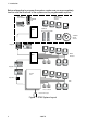
1. Introduction 1. INTRODUCTION The 9750 is designed to be fully programmable to suit individual site requirements and user needs. The system comprises a control unit in a metal case, up to four separate keypads and one keyswitch interfaces (see Figure 1 on the next page). You should always fit at least one keypad. The control unit provides: ° A four-wire bus connection for keypads, keyswitches and hardwired or wireless zone expanders. ° Connections for eight Closed Circuit zones.
1. Introduction Before attempting to program the system, make sure you are completely familiar with the functions of the system and its programmable options. 725rEUR Telecommand 715rEUR Wire free PIR detector 726rEUR PA 9955 735rEUR Universal transmitter 719rEUR Smoke detector Keypads Wired Detectors 9855 Keypads Control Unit Keyswitch PIRs Door contacts Fused mains spur Figure 1.
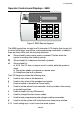
1. Introduction Operator Controls and Displays - 9930 Figure 2. 9930 Remote Keypad. The 9930 keypad has a single line 16 character LCD display that shows first to alarm information, level status, and programming commands. In addition there are three LEDs with the following functions: a Glows steadily when mains power is present. Flashes when the system is working from battery backup. f Glows steadily if a telephone line fault is present.
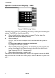
1. Introduction Operator Controls and Displays - 9925 Figure 3. 9925 Arming Station. The 9925 arming station is intended for use solely in setting and unsetting the system. The 9925 has the following LEDs: a Glows steadily when mains power is present. Flashes when the system is working from battery backup. s Glows steadily if: a) A PA, Fire, 24 hour or tamper circuit is active while the system is unset. b) The system needs an engineer or remote reset. c) A telephone line fault is present.
1. Introduction System Features Detectors The control unit provides connections for up to eight separate detector zones. Each zone can be connected as a four-wire closed circuit loop (CCL). See "4. Programming - Programming Commands" for the factory default settings and instructions on how to change the zone types and attributes. 9755 Hardwired Expander The 9755 expander provides an extra eight CCL zones to give a total of 16 zones.
1. Introduction User Control The control unit provides eight independent user access codes and a separate Duress code. The user can change these codes at any time, but cannot program the system with these codes. The user can set the system in the following modes: Full Set All the zones function as programmed during installation. Part Set B Selected zones are omitted. You must program the zones to be omitted during installation. Set with Omit One or more zones temporarily omitted.
2. Technical Description 2. Technical Description Specification Operating temperature = -10° to +55°C Humidity = 96% RH Dimensions = 243mm W, 234mm H, 87mm D Weight = 2.45 kg (without stand-by battery) Conforms to EN50131-1 Grade 1 and current BS4737 Part 1 for remote signalled systems, ACPO-IAS Policy, NACOSS NACP14, ABI log requirements. Power Supply System power supply Control unit power 9930 Remote Keypad Standby Battery = 230VAC (ambient Temp. 20°.
2. Technical Description Control Unit PCB and Case Figure 4 shows the layout of the control unit PCB. AC from transformer 12V Aux fuse Outputs Battery fuse Battery connector Aux Power Reset pins Connector for Plug-by communicator Tamper switch Zones Telephone line for built-in communicator Telephone Connector for built-in communicator Keypad and expander bus Figure 4.
2. Technical Description 9755 Expander The 9755 Expander provides connectors for eight four-wire CC loop zones. Figure 5 shows the layout of the PCB. Zone Connectors CCT9 Keypad bus CCT10 CCT11 CCT12 DATA Lid Tamper switch CLK CCT13 12V CCT14 Spare Connectors 0V CCT15 Spare Connectors (Not connected) SPARE CCT16 A/T SPARE Figure 5.
2. Technical Description Compatible Equipment 715rEUR-00 719rEUR-00 725rEUR-00 726rEUR-00 735rEUR-00 746rEUR-00 747rEUR-00 9925EUR-00 9928EUR-00 9930EUR-00 9755EUR-00 9955EUR-00 956UK-00 10 Radio PIR. Radio Smoke Detector. Radio Remote Setting Device. Radio PA. Universal Transmitter. 868MHz Test transmitter. 868MHz Go/No Go test receiver. Arming Station. Keyswitch interface. LCD Keypad. Hardwired eight zone expander. 868MHz "Class VI" radio expander. Downloader.
3. Installation 3. INSTALLATION Note: The following instructions assume that you have already run the necessary cabling. Caution: Always remove mains power before opening the case lid. Do not work inside the control unit with mains power present. Fitting the System Fitting the Control unit Case 1. 2. 3. 4. Remove the control unit case from the packing. Remove the front screws and slide off the case lid. The upper part of the case back provides a central keyway. Mark and drill a hole for the keyway.
3. Installation 6). Make sure that the bottom left corner of the PCB is seated on its support pillar. Fitting a 9930 LCD Keypad The backplate of the 9930 LCD keypad contains an adjustable cam that you can use to make sure the tamper switch will operate correctly when the keypad is mounted on an uneven surface. Figure 7 shows the backplate and the position of mounting holes. Adjustable Cam Figure 7.
3. Installation 6. 7. Mount the front of the keypad (containing the keypad pcb) onto the backplate and make sure that the tamper switch operates. If the tamper switch does not operate then rotate the cam until the tamper switch operates correctly when the front of the keypad is mounted on the backplate. Fitting a Remote 9925 Arming Station Figure 8 shows the 9925 Arming Station. 1. If necessary, lift the flaps on the faceplate of the keypad and undo the four screws holding on the back of the case. 2.
3. Installation Wiring the Control Unit Cable Entries The control unit case back provides several cable entries. The back is designed to stand away from the wall to leave space for cables. Mains Connection The control unit must be permanently connected to a spur outlet fitted with a readily accessible disconnect device. Connect the mains supply to the control unit using the 3-way terminal block located in the control unit back. Secure the mains cable to the case anchor point using the cable tie provided.
3. Installation Remote Keypads Keypad Addressing The 9750 control unit is supplied with one remote keypad. If you have fitted more keypads then each one must be given a separate "address". Links LK2 to LK4 set the keypad address, as shown in Figure 10. Keypad 1 Address Keypad 2 2 2 2 3 3 3 4 4 4 Keypad 3 Keypad 4 2 2 3 3 4 4 ON BACKLIGHT ON BACKLIGHT Backlight ON ON BACKLIGHT Backlight OFF Figure 10. Keypad Addressing.
3. Installation Connecting Keypads Figure 11 shows the connections for any of the remote keypads. Exit Terminate Button To connect an exit terminate button use the "ET" connector terminals on the keypad PCB. See Figure 11. Sounders Figure 11 shows the connections for the internal and external sounders. Typical Internal Sounder 16 Ohm Loudspeaker (2 Max.
3. Installation Detector Circuit Connections The left hand edge of the main PCB provides 14 connectors that can be used for up to 8 zones. Four Wire CC Connections Figure 12 shows how to connect four wire CC zones. Note that pairs of alarm contacts share contacts. You should wire the tamper contacts of all detectors in series and then connect them to the contacts marked "A/T".The control panel provides enough connectors for eight four wire circuits.
3. Installation Using Programmable Outputs OP1, 2 and 3 are "pull down type" outputs that provide negative applied control signals. The system adjusts the output polarity when you select the output type. Use programming command 81 for OP1, command 82 for OP2 and command 83 for OP3 (see "4. Programming"). Figure 14 shows some example applications for OP3.
3. Installation Wiring Keyswitches Figure 15 shows the connections for a 9928 Keyswitch Interface. Note: You can fit only one keyswitch interface per system. Momentary or Continuous Keyswitches The 9928 keyswitch interface can be connected to either momentary or continuous keyswitches, see Figure 15. When using a momentary keyswitch remove the jumper from link M/C. When using continuous keyswitches fit a jumper to link M/C.
3. Installation Installing a Communicator The 9750 control unit contains a built in communicator on the main PCB. In addition the control unit can be connected to a separate communication device using a wiring harness connecting to interface pins on the main PCB. Built in Communicator The built in communicator is a 300 Baud Auto Dialling Modem.
3. Installation If either of these functions detect a failure the system gives a programmable Line Fault Response (programming command 106). Statutory Information Application The built in communicator is suitable for connection to the following type of networks: (a) Direct exchange lines (PSTN) supporting DTMF (tone) dialling. (b) PABX exchanges (with or without secondary proceed indication).
3. Installation against which approval was granted. Note the approval label on the main PCB. REN The Ringer Equivalence Number (REN) of the built in communicator is 1. As a guide to the number of items of apparatus which can be simultaneously connected to an exclusive line, the sum of the REN values should not exceed 4. A BT provided telephone is assumed to have a REN value of 1. Safety Notice 21VAC from Transformer S.E.L.V. cct OP3 OP2 OP1 12V 0V TR + LS 12V AUX 12V AUX Battery Connector S.E.L.V.
3. Installation The terminals on the 9750 control unit main pcb are described as Safety Extra-Low Voltage circuits (SELV), according to the definitions in Safety Standard EN60 950. The terminals on the built in communicator are described as SELV or Telecommunications Network Voltage (TNV) according to the definitions in Safety Standard EN60 950. Note: The SELV and TNV connections which are shown in Figure 16 are for reference only and do not appear on the 9750 main pcb.
3. Installation Caution: The connection of only one such series apparatus is allowed to be connected between a main apparatus (e.g., telephone) and the PSTN. Take care to ensure that the A and B line are connected correctly ( i.e. correct polarity). The built in communicator continuously monitors the line for Ringing tones. Primary Line A 2 or B B 5 or A Diverted Line B1 A1 BT master Box (Exclusive Line) Telephone line to other equipment for example: Fax, answer machines. Figure 17.
3. Installation Figure 18. Fitting a Plug ByCommunicator 4. Make any necessary connections from the communicator to the Comms Wiring Harness. Figure 19 shows the outputs available on the free ends of the Comms Wiring Harness. 1 (Brown) Fire. -ve applied (+ve removed) in alarm 2 (Orange) PA. -ve applied (+ve removed) in alarm 3 (Yellow) Burg. -ve applied (+ve removed) in alarm 4 (Green) Open/Close. -ve applied (+ve removed) in alarm 5 (Blue) Alarm abort.
3. Installation If the system has already been installed: 7. Re-connect the battery. 8. Fit the case lid (don't forget to attach the earth lead from the case to the left hand support pillar). 9. Apply mains power. 10. Test communicator operation. Fitting a Battery Fit a rechargeable battery into the back of the case. The case provides space for a 12V 7AH battery. Make sure the battery terminals are oriented in the position shown in Figure 20. 7AH Figure 20.
3. Installation Initial Start Up Before applying power to the control unit, ensure that any remote keypad(s) have been addressed, and expanders, zone circuits and sounders are connected. 1. Connect the battery to the control unit PCB. The green power LED flashes and the internal sounder may sound. Ignore any other display at this stage. 2. Key-in the factory default user access code: 1234. The internal sounder stops. Ignore any other display at this stage. 3.
3.
4. Programming 4. Programming Entering Programming Mode “3. Installation - Initial Power Up” describes how to enter programming mode for the first time in a new installation. If you wish to enter programming mode at any other time: 1. Make sure the system is unset. 2. Press 0, then key in the Engineer’s code (default 7890). Installer Mode The display shows: You are now in programming mode.
4. Programming To change: Key-in: Notes YY Default Zone nn nn ab (Note: for zones 1 to 9 key in “01” to “09”.
4.
4. Programming To change: Key-in: Level A Exit Time Entry/Exit Volume CSID Code Set Time and Date Abort reset 44 45 Y Y Level B Entry route 61 Y Level B Exit Mode 62 Y Level B Alarm response 63 Y Level B Exit Time 32 10 Seconds 20 seconds 30 seconds 45 seconds 60 seconds 120 seconds 0 n No Entry/Exit tones from Loudspeaker EE tone volume from LS (1=low, 9=max) Y n....n Seed code for remote reset 51Y .....
4. Programming To change: Key-in: Output 1 Type, one of 81 Y Output 2 Type, one of 82 Y Output 3 Type, one of 83 Y Dual ply entry 86 Y Dual key PA (Incl.
4.
4.
4. Programming Leaving Programming Mode When all programming has been completed: 1. Key-in ‘99 Y’ at the keypad The display shows: 2. Press Y. The display shows: followed by the time and date. 99:Exit Eng ? 99:Checking Sys The system is now in user mode. Note: If there is a fault on the system , for example an open tamper circuit, the display shows this and will not return to Day mode. Press Y (Clear) and rectify the faults. Engineer Reset To perform an Engineer Reset: 1.
4. Programming Restoring All Factory Default Programming If you wish to restore all factory default options then: 1. Enter programming mode (if you are not already there). 2. Key in 98 Y at the keypad. The display shows: 98:Load 3. 4. Default Press 1. (You can press X to stop the procedure if you change your mind at this stage.) Press Y. The keypad gives a double confirmation tone and the system loads the factory default command values, erasing all previously programmed values.
4. Programming alarms operate whether the system is set or unset and cannot be omitted, and will always trigger communications if fitted. Normal Alarm (NA) (Key in 3) A zone programmed as ‘Normal Alarm’ will start an alarm when the system is set. 24 Hr Zone (24) (Key in 4) This zone causes an internal alarm if violated when the system is unset, and a full alarm if the system is set. Providing the Installer programs 24hr zones with ‘Omit Allow’, the user can omit 24 hour zones in Day mode.
4. Programming Chime (C) (Key in X1) When enabled by the user, the system gives a non-alarm warning tone when any zones programmed as ‘Chime’ are opened. This facility operates only while the system is in Day. Notes: 1. ‘Chime’ is available only for Normal Alarm, Final Exit, Entry Route and Shock Analyser zone types. 2. To make chime available from the keypad sounders but not the internal sounder then program command 22 with option 0.
4. Programming adjust the sensitivity you must enter the complete command, for example to change the sensitivity to 3 you must key in: X7 + 3. Change Engineer Code (Command 20) To change the Engineer access code: 1. Make sure you are in programming mode. 2. Key in 20 and press Y. The display shows: 3. 4. Key in a new four digit Engineer access code. The display shows: 20:Code 20:Code **** Press Y. Loudspeaker Chime (Command 22) A user may find that the chime tone from the keypads is not loud enough.
4. Programming Local Sounder Delay on Entry (Command 26) Use option 1 (default) to delay local sounders for silent communications when an entry alarm is triggered (required by some police forces). This option is only valid if you have programmed a Bell Delay. Use option 0 for no delay. Exit Fault External Sounders (Command 27) When programmed with option 0 of this command the system operates the internal sounders if the user tries to exit while a zone is still violated (for example a door is not shut).
4. Programming PA Reset (Command 34) If you wish to make the system engineer reset after a PA alarm then use option 1. For user reset use option 0. First Circuit Response (Command 35) If you select option 0 (Lock out) then the complete system rearms at the end of the programmed bell run time, but excludes the first zone to activate during the set cycle.
4. Programming system by pushing an exit terminate button connected to a keypad. Note that the exit time is infinite in this option. Option 2: Final door set. Use this option to complete setting the system by closing a door fitted with a Final Exit zone detector. Note that the exit time is infinite in this option. If a PIR detector covers the final exit door then selecting Final Door Set is not recommended: exit faults may occur if the detector responds to transient drafts caused by the door closing.
4. Programming strates the volume of the tone when you enter the digit. CSID Code (Command 50) To allow the customer to use the ‘Remote Reset’ facility, you must program the control unit as ‘Engineer Reset’ (Command 33 option 1) and then install a four digit Central Station Identification (CSID) code. First make contact with the central station and obtain the CSID code, then ensure that the system is in programming mode. Key in: 50 Y nnnn Y Where nnnn is the "CSID Code".
4. Programming “Installer Mode”. The system sets its internal clock/calendar to the time you have given it. Abort Reset (Command 53) Option 0 ensures that reset after abort is the same as system reset (see Command 33). Option 1 enables customer reset after an abort if they unset the system within 90 seconds of the alarm. Level B Final Exit Response (Command 60) Command 60 controls how the system will treat Final Exit zones in Part Set Level B.
4. Programming Level B Exit Time (Command 65) This command sets the exit time for Level B. See “Programming Commands” for options. Output Programming (Commands 81, 82 and 83) The system has three transistorised, high current, programmable outputs. Command 81 programs output 1, command 82 programs output 2 and command 83 programms output 3. All three commands take a single following digit describing the function. Note: The outputs are a "pull down” type that provide negative applied control signals.
4. Programming Ready Lamp 24 Hour alarm Strobe Smoke Reset (Key in 6) This output is active when the system is in Day, and if there are no faults. The output is inactive when the system is full or part set, during any alarm, or if a circuit fault prevents setting. Note that the output will also be active when the control unit is in programming mode. (Key in 7) This output will become active if a zone designated as ’24 Hours’ is violated. The output deactivates when the system is disarmed.
4. Programming Load Full Defaults (Command 98) Use this command to load default values for all commands. 1. Enter programming mode (if you are not already there). 2. Key in 98 Y at the keypad. The display shows: Load 3. 4. Defaults Press 1. (You can press X to stop the procedure if you change your mind at this stage.) Press Y. The system loads the factory default command values, erasing all previously programmed values. Notes:The log is protected and cannot be erased by the Installer.
4. Programming Dual (3) then close down and dial the second telephone number and attempt to connect to the remote receiver. If received and acknowledged on this attempt, the system will close down and the alarm transmission will be complete. If the system fails to connect to the second telephone number, it will close down again and re-attempt to connect to the first telephone number. The system will continue to shuttle between the two numbers up to 15 times.
4. Programming Entering a valid access code silences the sounders and the displays indicates a telephone line fault. The system can be set again with the line fault present. Note: Audible response is the NACOSS recommendation for line fault. Silent (2) If the system is set then the control unit logs the event but the keypads do not give any tone or display. The control unit cancels any programmed bell delay if the line is out of order when an alarm occurs.
4. Programming (which represents the “R” or Recall button on a telephone) which is detected by the exchange as a request for a new clean line. With the new line available, the communicator then attempts to connect to the pre programmed receiver number. Download Mode (Command 110) The 9750 can be programmed from a PC using software. You can connect the PC to the control unit over the telephone network. Key in 110 Y Y to manually accept a call from the PC.
4. Programming Access Mode (Command 114) This function allows you to provide extra security when a remote PC is dialling into the system. Once the PC is connected to the system then the has access to all system programming commands. If you wish to provide secure access then either use Option 0 or Option 1 below. Alternatively you can use command 110 if you want an engineer present to provide access for a remote PC connection to the panel.
4. Programming The system can store telephone numbers up to 31 digits long. You can use the A key to insert a pause (four seconds). To enter a number: 1. Enter programming mode (if you are not already there). 2. Key in 115 (or 116) Y at the keypad. 115:Tel The display shows (for example): No 1_ 3. 4. Press Y. Key in the digits of the number. If necessary press D to move the cursor to the left to edit or delete the number. Press C to move the cursor to the right.
4. Programming Fast Format Channels (Command 121) If you selected Fast Format reporting type in command 103 then you can use command 121 to allocate one of the following events to each of the 8 channels: 0 Not used 8 Detector Low Battery 1 Fire 9 Supervision Loss 2 PA X1 RF Jamming 3 Burglar X2 AC Fail 4 Open/Close X3 Tamper Alarm (Day tamper) 5 Alarm Abort X4 Open (see note 1) 6 Technical Alarm X5 Close (see note 1) 7 Alarm Confirmation X6 Zone Omitted (see note 2) Notes:1.
4.
4. Programming The system also provides a “custom” mode which allows any combination of event information. However, you must use to create the combination required. SIA alarm transmissions will take considerably more telephone time than Scancom Fast format since the system transmits extended alarm data to the central station. Modem Tone Format (Command 132) If you select SIA format in command 103 then you can use command 132 to select the modem tones used by the plug-on communicator.
5. Testing 5. Testing Reading the Log (Command 90) The control unit keeps a 250 event log of recent events. Each event is represented by a two digit code, shown on the next page. To review the event log, make sure the system is in programming mode, then: 1. Key in 90y. The display shows the most recent event in the log. For a list of the log codes see the next page. 2. Key in 1 to show earlier events or 3 to see more recent events. 3. Press y to toggle between the event message and the event time. 4.
5.
5. Testing Engineer Walk Test (Command 97) Allows the engineer to test all devices on the system. 1. Enter programming mode. 2. Key in 97 Y The display shows: 3. 97: Walk Test Open and close each alarm and tamper contact in turn. The system gives a chime tone each time you open and close a detector contact. The displays shows: "A:Zone:" and the zone number of every detector you have tested (note that the display displays each zone number for one second, in sequence).
5.
Index Index 115, 116 ................................................................. 52 117 ........................................................................ 53 118, 119 ................................................................. 53 121 ................................................................. 35, 54 122 ........................................................................ 54 126 ........................................................................ 54 131 .....................
Index D K Defaults ................................................... 30 Dial restoring ................................................................ 37 Keypad addressing ............................................................ 15 backlight ................................................................ 15 backplate ............................................................... 12 connection ............................................................. 16 current ............................
Index P PA ...................................................... 5, 10 PA reset .................................................. 42 Panic Alarm ................................ 5, 10, 37 Part set ..................................................... 6 Part set B ................................................ 39 Pause ...................................................... 53 PBX ......................................................... 21 Personal Attack .................................. 5, 10 PIR ...
Index 64 496478
Cooper Security Ltd Security House Xerox Business Park Mitcheldean Gloucestershire GL17 0SZ Product Support (UK) Tel: (09068) 616343 Between 09:00 and 17:30 Monday to Thursday, 09:00 to 17:00 Friday (CALLS CHARGED AT 60p PER MINUTE) Product Support Fax: (01594) 545401 Part Number 496478 Issue 1