M-Series Manager's Manual
© Cooper Security Limited 2007 Every effort has been made to ensure that the contents of this book are correct. However, neither the authors nor Cooper Security Limited accept any liability for loss or damage caused or alleged to be caused directly or indirectly by this book. The contents of this book are subject to change without notice. Should the content of this manual not reflect the core functions of the product please let us know. You may be able to obtain more recent issues of this manual on: www.
Contents Preface...........................................................................................................2 Introduction....................................................................................................................2 Accessing the User Menus..............................................................................................3 Options in User Menu 1 ..................................................................................4 Option 1-1: Testing..........
Preface Introduction About your Alarm System Your intruder alarm system provides comprehensive and flexible protection for domestic or commercial premises. The system comprises several components, such as keypads and sensors, linked to a control unit, which is concealed from view but accessible for maintenance. About this Manual This manual describes the functions available from the two user menus.
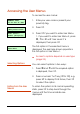
Accessing the User Menus To access the user menus: BANNER TEXT 17:30 Sun 01 JAN 1. Enter your user code or present your proximity tag. 0=Set Selection [Ent]=User Level 2. Press [. User Level 1 Press [Ent]or[2] 3. Press [ if you want to enter User Menu 1. If you want to enter User Menu 2, press |, ¬ or 2 until "User Level 2" is displayed, then press [. User 1 Menu 1 Test Menu The first option in the selected menu is displayed. The example shown opposite is the first option in User Menu 1.
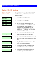
Options in User Menu 1 Option 1-1: Testing Option 1-1-1: Testing the Bell 1. Press [ to select this option. User 1 Menu 1 Test Menu Test Menu Bell Test 4 This option enables you to test the internal sounder, strobe, external sounder, and telecommands. 1 2. Press [ to select Bell Test. Bell test wards: Ward > 1*...... 3. Use the numeric keys to select the wards to test, then press [. Any ward numbers shown will be tested. (A “*” indicates that the ward will not be tested, and “.
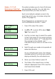
Option 1-1-2: Performing a Walk Test This option enables you to check that zones are operating correctly. You can test only those wards that you have access to. Each zone tested is added (once) to the event log, which you can review using User option 2-9 (page 37). Zones triggered on a walk test are not communicated to the ARC, if used. 1. Press [ to select this option. User 1 Menu 1 Test Menu Test Menu Walk Test 2 2. Use | or ¬, or press 2 to select Walk Test, then press [. Walk test wards: Ward > 1*.
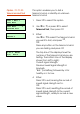
Option 1-1-3: Telecommand Batteries This option enables you to check if any telecommands have reported a low battery. User 1 Menu 1 Test Menu 1. Press [ to select this option. Test Menu 3 Telecmd Batts 2. Use | or ¬, or press 3 to select Telecommand Batts, then press [. No batteries low Either: The display shows that all telecommands are OK. 2:01:01 Batt Low Martha’s OR The display shows the number of any telecommands that have reported a low battery.
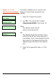
Option 1-1-4: Telecommand Test 1. Press [ to select this option. User 1 Menu 1 Test Menu Test Menu Telecmd Test 2:01:1 RNode Martha’s 2:01:3 RNode 9(5) Bat-H This option enables you to test a telecommand, or identify an unknown telecommand. 4 2. Use | or ¬, or press 4 to select Telecmd Test, then press [. 3. Either: Use | or ¬ to select the telecommand you want to test, and press [. OR: Press any button on the telecommand you are testing and press [.
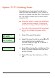
Option 1-2: Omitting Zones Sometimes you may need to omit zones when you set your wards, e.g. if a zone is to remain occupied while the rest of the ward is set. This option enables you to select which zones to omit. User 1 Menu 2 Omit Zones 0001 is Armed 0002 is Armed Z When the system is unset, any selections made here are cleared. This prevents zones from being omitted inadvertently. Z You can omit only zones that have been set up as omittable (Engineer option 1-1). 1.
Option 1-3: Shunting 24hr Zones This option enables you to shunt (disable) all 24 Hour zones in selected wards that have been set up as shuntable in Engineer option 1-1. Shunting disables a zone and the shuntable attribute identifies whether this is permissible. Z Zones remain shunted until you use the Reinstate 24hr option (see below). Z Reinstating zones may start the exit timer, depending on whether Unshunt, No Exit or Unshunt & Exit is selected (Engineer option 1-9-1).
Option 1-4: Changing your User Code This option enables you to change your own user code. To make changes for other users, refer to page 21. 1 User 1 Menu 4 Change Code 1. Press [ to select this option. Enter new code.. ---- 2. Enter your new code, e.g. press 5 6 7 8, then [. Z If your new code is not accepted, the display shows "NOT ACCEPTED try a different code". This usually means that the code is already in use. Press r enter the code again.
Option 1-5: Enabling Chimes This option enables you to select which of your wards (if any) use the chime feature. In a ward with this feature enabled, zones that have a Chime Tone attribute (User option 25) and are in a selected ward will generate a chime tone when activated. The wards then remain chime-enabled until you deselect them with this option. A zone may generate a single, double or triple chime, depending on the Chime Tone attribute selected in User option 2-5.
Option 1-6: Setting the Speaker Volume This option enables you to adjust the volume level of the extension loudspeaker connected to the control unit. User 1 Menu 6 Volume Control 1. Press [ to select this option and display the current setting. Volume Control >>>>>>> (MAX) 2. Press | and ¬, or enter a value (0 to 7), to adjust the volume, from ‘Sound Off’ up to maximum. 3. Press [ to accept the displayed value or ] to exit without change.
Option 1-7: Customising Text This option enables you to edit the following text strings: Banner Text This message is shown on the top line of the display when the keypad is in normal "standby" mode (i.e. waiting for a code to be entered). Group Names These are the names of the ward groups (see page 36). The names are displayed when setting ward groups (see the User's Guide). Telecommand Text These are the names of any telecommands that the installer has allocated to your system. 1.
Option 1-8: Setting Up Silent Set Wards This option enables you to select which of your wards (if any) set silently, without emitting an exit tone, when the system is set normally. The wards remain enabled for silent setting until you deselect them in this option. Z 1 Pressing 8 when the display shows "0=SET WARDS" can set all your wards silently, irrespective of their setting here1. User 1 Menu 8 Silent Set Wards 1. Press [ to select this option. Silent set wards Ward > **...... 2.
Option 1-9: Configuring Engineer Access This option enables you to define a period during which an engineer can log into the alarm system. Once the period has expired, the engineer can continue working if logged in but will not be able to log in again. The period starts from the time you set it and can be four hours or five minutes. You can terminate the period at any point. Z User 1 Menu 9 Engineer Access The default setting is Infinite. 1. Press [ to select this option. 2.
Option 1-0: Accessing the Set/Unset Menu The set/unset menu is displayed whenever you enter your user code or present your proximity tag. This option enables you to access this menu from User Menu 1. The Set/Unset Menu has several options, but only relevant ones are shown, e.g. if all wards are unset, the option to unset wards is not shown. For information about setting, unsetting and resetting the system, refer to the User's Guide.
Options in User Menu 2 Option 2-1: Viewing Zones This option enables you to view the status of each zone, which may be: Healthy The normal status of a zone (e.g. a door is closed or a detector inactive). Active The alarm status of a zone (e.g. a door is open or a detector is triggered). Tamper The interference status of a zone (e.g. a cable has been cut or a cover has been removed from a detector). Shorted The short-circuit status of a zone (e.g. a cable has been shorted or damaged).
Option 2-2: Setting the Time and Date This option enables you to set the system time and date. Z 1. Press [ to select this option. User 2 Menu 2 Time and Date Time and Date Set Time Enter new time:11:44 The system automatically advances/retards the time by one hour at 1 am GMT on the standard summer/winter changeover dates. 1 2. Use | or ¬, or press a hot key (1 or 2) to select Set Time or Set Date, then press [. 3.
Option 2-3: Setting Up Shunt Groups Shunt groups provide a simple way to isolate zones until further notice. Each shunt group can contain up to eight zones, and each group can be allocated to a "Shunt" user code. When the code is first entered, the zones are isolated. When the code is entered again, they are reinstated. Although 24-hour zones are most commonly isolated, any zone can be assigned to a shunt group. Z Any zone selected must have the Shuntable attribute set in Engineer option 1-1.
You can view any of the eight possible zones assigned to the group by using | or ¬, or pressing the hot key (1 to 8). If you want to delete the displayed zone from the shunt group, press r, then ]. You can delete more than one zone by scrolling to each in turn and pressing r, then finally pressing ]. Group 01 Zone >1 Zone >---- 4. Press [ if you want to edit the zone number. You will see that the bottom line contains a ">" to indicate that you are in edit mode. 5.
Option 2-4: Setting Up User Codes This option allows you to define users to operate the alarm system. When setting up a user, you need to specify: • A user code. This is the code that the user enters at keypads (e.g. to set or unset the system). • A user type (e.g. Manager). This determines, for example, the range of user options the person can access. The user’s access to menu options is initially determined by the user type selected, but can be customised, if required (see page 27).
About the User Types Manager 1 Standard Global 2 The following user types are available. (Press the key shown next to the type name to select a type directly.) Users of this type have access to all user menus and options. They can set and unset assigned wards from any keypad. By default, user 001 is set up as a manager, with a default user code of 5678 (567800 when using six-digit codes). Users of this type have access to User Menu 1, options 0, 1, 2, 3, 4, 5, 8 and 9.
Easy Set 5 When unsetting, all associated wards are unset and the keypad displays no options. The system sets with no options, providing auto-set wards are set up. The user can set/unset from any keypad. Z You must set up wards assigned to an Easy Set user as auto-set and autounset, see page 26 onwards. Reset Only 6 Users of this type have access to User Menu 1, options 1, 2, 3, 4, 5, 8 and 9. They can reset 24-hour alarms from any keypad.
Allow setting in Engineer option 1-9-1-24 must be set to YES. Access 9 Users of this type have no access to user menus and cannot set or unset the system. Entering a user code of this type temporarily activates outputs of type "Code Accepted", Access or "Access Code", which could be used to operate electric door strikes or similar mechanisms. Shunt Users of this type have no access to user (No hotkey available.) menus and cannot set or unset the system.
Option 2-4-1: Configuring the User Codes 1. Press [ to select this option. User 2 Menu 4 Edit Codes User Codes Code This option enables you to set up or modify users. For each user, you specify information such as the user type and the wards the user has access to. 1 Define new users User no. 05 2. Press [ to select Code. 3. The lowest available user number is displayed. You can press [ to select this user. Alternatively, you can select a different user by entering a number or by using | or ¬.
User 05 wards Ward > 1*...... 6. Use the numeric keys to select the wards you want the user to have access to, then press [. Any ward numbers shown will be allocated to the user. (A “*” indicates that the ward will not be allocated, and “.” Indicates that you have no access to the ward.) Z If the Local Setting option is selected in Engineer option 1-9-1, a user can set a ward only if the keypad is assigned to that ward. 05 Auto Sets:Ward > 1*...... 7.
Option 2-4-2: Defining User Names 1. Press [ to select this option. User 2 Menu 4 Edit Codes User Codes User Name This option enables you to specify a name for each user. When viewing the event log (page 37), pressing r toggles between displaying user number and user name for appropriate log entries. 2 2. Use | or ¬ or press 2 to select User Names, then press [. User 01 User 01 3. Select the user by using | or ¬ or by entering the user number, then press [. User 01 ^ser 01 4.
Menu 1 Options:> 0123456789 4. Select the User Menu 1 options to which the user should have access, then press [. Pressing 0 to 9 selects (option number displayed) and deselects (“*” displayed) options. The options are: 0 = Set/Unset Menu 1 = Test Menu 2 = Omit Zones 3 = Shunt 24hr Zones 4 = Change Code 5 = Enable Chime 6 = Volume Control 7 = Customise Text 8 = Silent Set Wards 9 = Engineer Access Menu 2 Options:> 0123456789 5.
Option 2-4-4: Programming Telecommands 2:01:1 RNode Telecmd 1 Cooper Security Limited recommend that you take advice from your alarm installer before modifying any of these options. 1. Press [ to select this option. User 2 Menu 4 Edit Codes User Codes Telecommands Use this option to allocate telecommand or PA buttons to individual wards. 4 2. Use | or ¬ or press 4 to select Telecommands then press [. 3. Select the telecommand or PA by using | or ¬, then press [.
allocated ward) only when in range of a specific MRNode receiver1. OR: Unused: The control unit will ignore any telecommand programmed as Unused, even though it may still be learned by an MRNode. (Hint: Use this option to disable telecommands that have been lost.) Press [ to save your changes. Button 1 ^Set Group 1> 1******* 6. Press [ to select this option. (Or, use | or ¬ to select other buttons.) Press 1 to 4 (or 1 to 8 on a M2000) to select the group that will be set by the button.
Telecmd 1 ^elecommand Name 9. Press [ to select this option. Use the text editing keys (page 48) to edit the telecommand name, then press [ to save your changes.
Option 2-5: Setting Up Chime Zones This option enables you to select which zones generate a chime if activated when unset, or to switch chimes off. The chime occurs only at keypads and extension loudspeakers assigned to the same ward(s) as the zone. Chimes must be enabled in User option 1-5. When a chime occurs, keypads display the zone number if configured by the Chime Visible setting in Engineer option 1-9-1. User 2 Menu 5 Edit Chime Zones 1. Press [ to select this option. Chime Zone: 0001 Disabled 2.
Option 2-6: Using Communications Option 2-6-1: Starting a Call Back 1 You can use this option to initiate a connection over the telephone line to a remote site that is running the Downloader software1. Once the communication link is established, the remote site can upload data and change settings in the control panel. The link continues until the remote site disconnects it. Z Select this option only if requested by your alarm company.
Option 2-6-2: Editing the Call-Back Numbers This option allows you to define or edit up to four telephone numbers for communication with a PC running the Downloader software1. User 2 Menu 6 Communications 1. Press [ to select this option. Communication 2 Edit Call Back 2. Press [ to select Edit Call Back. Edit Call No. 08700543678 3. Use | or ¬, or press a hot key (1 to 4) to select the number to edit, then press [. 1 4. Enter the telephone number. 08700543678 ^dit Call No.
Option 2-7: Assigning Zones to Wards The assignment of zones to wards is usually carried out by your alarm company. Change these assignments only if you have detailed knowledge of your alarm system and the way that wards are used in it. Z You can assign zones only to wards assigned to your user code. User 2 Menu 7 Configure Wards 1. Press [ to select this option. 0001 Ward : 1....... 2. Press | or ¬ to scroll to the zone, or enter the zone's four-digit number, then press [.
Option 2-8: Setting Up Ward Groups This option enables you to allocate wards to groups, which you can then set or unset with a single operation (as described in the User's Guide). Z You can select only those wards that are assigned to your user code. Z You can name each ward group using User option 1-7 (page 13). User 2 Menu 8 Edit Groups 1. Press [ to select this option. Viewing Group 1 Ward : ........ 2. Use | or ¬, or press a hot key (e.g. 4) to select the ward group to edit, then press [.
Option 2-9: Using the Log Option 2-9-1: Viewing the Log This option enables you view the contents of the system log. The log contains the date and time of system events, such as wards being unset, zones omitted, duress code activations and communications problems. For more information about the event codes displayed, see page 52. The number of events recorded in the log is model specific. 1. Press [ to select this option. User 2 Menu 9 Log Log Functions View Log 1 2. Press [ to select View Log.
Option 2-9-2: Printing the Log 1. Press [ to select this option. User 2 Menu 9 Log Log Functions Print Log If a printer is connected to the control unit, you can print some or all of the events recorded in the log. 2 2. Use | or ¬, or press 2 to select Print Log, then press [. How many events? 0030 3. Choose the number of events to print by using | or ¬, or by entering the fourdigit value, then press [. With offset of:0030 4.
Option 2-9-3: Viewing the Access Log You can use this option to view the content of the access log, which stores every use of a user code of type Access (which is used to open doors). User 2 Menu 9 Log 1. Press [ to select this option. Log Functions 3 View Access Log 2. Use | or ¬, or press 3 to select View Access Log, then press [. Name :- User 02 02:35:48 01/05 3. Use | or ¬ to scroll through the events (| displays earlier events). 4. Press ] to exit.
Option 2-0: Setting Up Timers Option 2-0-1: This option enables you to define up to Setting Up Time Switches three time switches, which can be used to switch outputs of the alarm system on or off at selected times. The outputs may, for example, control internal or external lighting or other electrical equipment. You can define each time switch to have up to three pairs of switch on/off times. You can also choose the days of the week that each of these operate.
Z Time Switch 1 On (1) >00:00 You can manually override a time switch by pressing 0, then pressing r to toggle its current status. 5. You will see a screen similar to the one shown opposite if you have chosen to edit an on/off time. The number in brackets indicates whether it is in the first, second or third pair of on/off times. Enter the time in 24-hour format, (e.g. 2100 for 9:00pm), then press [. Continue from step 4 or press ] to exit. 1 Operates On :> .............. 6.
Option 2-0-2: Setting Up Auto-Set Timers Use this option to make the control unit set or unset selected wards at specified times. The control unit has three auto-set timers. You can allocate each timer to one or more wards, which the control unit sets and unsets at the times you chose. For each auto-set timer you can specify up to three events. Each event comprises a switch on (set) time, an off (unset) time, and a day of the week.
Auto Set 1 Auto Set On (1) 1 00:00 3. Use | or ¬, or press a hot key (1 to 3) to select the auto-set timer to edit, then press [. (The display shows the timer number at the top right.) Each auto-set timer has three events. The display shows the event number in brackets on the bottom left. For each event, you can specify the on (set) time, the off (unset) time and the days of operation. 4. To select the on/off time or days of operation to edit, EITHER Use | or ¬ then press [.
When editing the days press 1 to 7 to toggle days on/off, then press [. 1 Operates On :> .............. On the days screen the event number is in the top-left corner. (Note that day 1=Sunday.) 6. Repeat steps 4 and 5 for each event you wish to program. Auto Set Ward > ** 1 7. To allocate wards to the auto-set timer press r. Use the numeric keys to select the wards then press [. The control unit allocates any ward numbers shown on the bottom line to the auto-set timer shown on the top line.
Option 2-0-3: Setting Up Code-Locks Timers Use this option to lock out one or more users at specified times. The control unit has three code-lock timers. You can allocate each timer to up to ten users. Each timer prevents the system from accepting the allocated users' codes at the specified times. If a user enters his/her user code while the code-lock timer is on, the display shows "Sorry. Your code is locked out". Each code lock timer has up to three events.
4. To select the on/off time or days of operation to edit, EITHER Use | or ¬ then press [. OR Press a hot key (1 to 9) then press [. The table below shows the hot keys for each item: Event 1 2 3 ON 1 2 3 OFF 4 5 6 Days 7 8 9 Codelock Group 1 On (1) >00:00 1 Operates On :> .............. 5. Enter the time in 24-hour format, (e.g. 2100 for 9:00pm), then press [. When editing the days press 1 to 7 to toggle days on/off, then press [. On the days screen the event number is in the top-left corner.
You can now: • Continue with step 6 to specify other users as necessary. • Press ] and continue from step 4. • Press ] twice to exit.
Text Keys The following table shows how to obtain characters when entering text at the keypad. For example, press 2 twice to obtain the "B" character. Once you have chosen the character you require, press | to move the cursor to the right to edit the next character. The ¬ key moves the cursor to the left. Note: When you reach the end of the character sequence, the next press of the same key takes you back to the beginning of the sequence.
Zone Numbering Each zone has a unique 4-digit number. The meaning of the number is as follows: For all zones except those using iD Plus biscuits (on an M800iD Plus): • • The first digit is the network number. This is the network number of the device that the zone is connected to (0 for zones connected to the control unit PCB). The number of available networks depends on the type of control unit.
Radio Systems You security system may be fitted with a radio receiver (called an MRNode) that ‘listens’ for signals from wire-free detectors and other transmitters, and reports their activity to the control unit. The control unit treats the wire free detectors as standard zones. All the options described in the existing Manager’s Manual work with wire free detectors in the same way as with wired detectors.
any programming of PA buttons, but you can give them a name and allocate them to individual wards. Telecommand Buttons The 722r, 723r, 727r and 728r telecommands have four buttons that you may program for separate functions. The control unit identifies each button on a telecommand by a number. The keypad display indicates these buttons by showing the numbers followed one of the symbols “^, <, > or v” to indicate the position of the button on the telecommand, as shown on the left.
Log Events Event --- NO EVENT --### LECS or REMS ### NODE R# ADD ### NODE R# LOST ### NODE R# TAMP ### NODE'S ### XNODE'S #### OFF TEST #### OMITTED #### REINSTATED #,## AUX FAULT #,## LEC LOST #,## LEC TAMPER #,## NODE ADDED #,## NODE FUSE #,## NODE LOST #,## NODE TAMPER #,## PSU FUSE #:## PSU TAMP #,## REM ADDED #,## REM LOST #,## REM TAMPER #:## RF CLEAR #:## RF JAMMED #,## XNODE ADDED #,## XNODE FUSE #,## XNODE LOST #,## XNODE TAMP 24 Hr WARDS:24H RESTORE ####24Hr ALARM #### 24HR OMIT:24HR REINST:ABORT
Event BEAM PAIR #### BELL BOX TAMPER BELL FUSE BELL TAMP OMIT BELL TESTED:BELLS ACTIVE:CHANGE CODE ### CHANGE TAG ### CHNG CODE #### CHNG TAG #### CNFG CHANGE #### CODE #### CODE LOCK # OFF CODE LOCK # ON CODE LOCKED #### CODE TAMPER COMMS FAILED COMMS TEST CALL CONFIG CHANGE ## DATE CHANGED AT DATE CHANGED TO DEFAULT USER DEFAULT USER #### DEFERRED SET:DL DISCONNECT FL) DL DISCONNECT OK DURESS CODE #### ENG HW DEFAULTED ENGINEER ARRIVES ENGINEER DEPARTS ENTRY TIME-OUT:ENTRY ZONE #### EXIT CANCELLED:EXIT ST
Event MASK TMP S #### MASK TMP U #### MENU TIMEOUT #### MODEM LOCKOUT NETWORK # FUSE NODE TAMP OMIT NORM. REST. #### OCCUPANCY SET ON LINE TO # ON-SITE RESTART PA WARDS:PANEL LID TAMPER PANEL STARTED PANEL TAMP OMIT PANIC ALARM #### PANIC CODE #### PANIC REST.
Event SHNT #### REINST SHUNT CODE #### SHUNT END #### SHUNT GROUP ## SHUNT START #### SHUNT ZONE #### SILENT PA #### SUMMER CHANGED SUMMER TIME SET T.SWITCH # OFF T.SWITCH # ON TAMP 1 OMIT TAMP ZONE #### TAMP. REST.
User Codes and the Log When displaying or printing the log, the control unit shows users as a number (shown in the table of log events as “####”). You can see this number when you set up a new user with option 2-4. The control unit reserves some user numbers for special purposes: User Engineer Manager Downloader Keypad PA System M50/600/ 750/800 000 001 050 051 052 Number M1000 000 001 100 101 102 M2000 000 001 251 252 253 If you are not sure what type of control unit your system has, don’t worry.
System Records General System Details Wards 1 2 3 4 5 6 7 8 Entry Time Exit Time Setting Mode Bell Delay Bell Duration Wards Entry Time Exit Time Setting Mode Bell Delay Bell Duration Remote Servicing (Downloading) Site Telephone No Details 1 2 3 User Authorised Y/N 57
Ward Groups Group Name Wards Group Name 1 2 3 4 5 Shunt Groups Group Zone 1 Time Switch 1 Timer On at Wards 6 7 8 9 0 Zone 2 Zone 3 Zone 4 Zone 5 Zone 6 Zone 7 Zone 8 Off at Mon Tue Wed Thu Fri Sat Sun Off at Mon Tue Wed Thu Fri Sat Sun Off at Mon Tue Wed Thu Fri Sat Sun 1 2 3 Time Switch 2 Timer On at 1 2 3 Time Switch 3 Timer On at 1 2 3 58
Auto-Set Timer 1 Timer Set at Unset at Mon Tue Wed Thu Fri Sat Sun Unset at Mon Tue Wed Thu Fri Sat Sun Unset at Mon Tue Wed Thu Fri Sat Sun Off at Mon Tue Wed Thu Fri Sat Sun 1 2 3 Set Wards: Auto-Set Timer 2 Timer Set at 1 2 3 Set Wards: Auto-Set Timer 3 Timer Set at 1 2 3 Set Wards: Code Lock Timer Timer On at 1 2 3 Users: 59
User Details No.
Zone Details Zone No.
Service Record Date 62 Engineer Action
Installer Information Installation Engineer: Installation Company: Address: Telephone Number: Reset Message: Alarm Receiving Centre: Telephone Number: Remote Reset Message: 63
Quick Reference BANNER TEXT 17:30 Sun 01 JAN 1. At the keypad, enter your user code or present your proximity tag. 0=Set Selection [Ent]=User Level 2. Press [ to access the user menus. User Level 1 Press [Ent]or[2] 3. Press | or ¬ to display user menu 1 or 2, then [ to select that menu.
NOTES 65
11751729