M2000 Installation Instructions MENVIER SECURITY
© Cooper Security Limited 2010 Every effort has been made to ensure that the contents of this book are correct. However, neither the authors nor Cooper Security Limited accept any liability for loss or damage caused or alleged to be caused directly or indirectly by this book. The contents of this book are subject to change without notice. Cooper Security Limited make every possible effort to update manuals and guides regularly to reflect changes in the product.
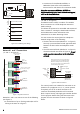
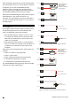
• Engineer keypad port. Introduction Figure 1 and Figure 2 show the layout of the control panel and the main features of the printed-circuit board (PCB). The panel includes a wealth of features, including: • Eight on-board zones. • Two network ports for the connection of keypads, MSNodes and MRNodes (see Figure 3). The additional network devices enable the system to be expanded up to 264 zones.
23 24 5 25 SK1 16 A B C/F D E/G REMOTE NETWORK 2 PSTN A1 B1 SK2 LED2 LED3 USB 22 LED4 6 9 PIN 1 LED1 Z2 T2 CIRCUIT 2 LED7 Z7 T7 CIRCUIT 7 17 LED12 LED13 Z8 T8 CIRCUIT 8 15 LED5 LED6 14 AC IN 0V 0V 12V 12V AUX 16 BATT 0v -3 +4 -5 12V TRANSISTOR OUTPUTS 1 LED9 LED8 SERIAL PRINTER 19 BACK TAMPER Z6 T6 CIRCUIT 6 FACTORY RESTART Z5 T5 CIRCUIT 5 18 + 0V REM LINE TRG STB TR- H/O H/O N/O N/C COM N/O N/C COM RELAY1 RELAY2 - BELL + SPKR RST FLT AUX TMP - LED10 0V 1 14V4 Z4 T
Network 1 2000 CONTROL PANEL Wiring Option 1 MSNodes Max 16 2 Outputs 100m max MSNode 1 1 Output 100m max 8 Zones Network 2 MRNode 2 MSPSU 16 8 Zones 1 km max to furthest MSNode 8 Zones An MSNode/MSPSU is capable of driving 4 Remote Keypads and a Loudspeake r NOTE: Do not connect an MSPSU, MSNode, or MRNode directly to the same network as an 100m max to MIDNode or keypad. furthest keypad Max 4 5 Outputs 8 Zones Engineer’s keypad (cannot have zones or outputs).
Fitting and Wiring Procedure To install the control panel: 1. Remove the front cover by releasing its three retaining screws and disconnecting the earth bonding cable from the spade connector on the transformer. Warning: mains voltages may be present at the mains terminal block (see Figure 1). 2. Connect any optional modules to the PCB. 3. Slide the back tamper switch mounting plate into the slots shown in Figure 1. 4.
Zone Wiring ("1" in Figure 2.) The control panel has a set of eight on-board terminal blocks for the connection of alarm sensors, such as door contacts and PIR detectors. Each terminal block can connect to one or more sensors, wired using either the double-pole (also known as Closed Circuit Loop, CCL) method (see Figure 4) or Fully Supervised Loop (FSL) method (see Figure 5). 100 Ohms Tamper Alarm Tamper Tamper Max.
• A maximum of 16 MSNodes, MSPSUs, or MRNodes. Please refer to the Installation Instructions for each device for connection details. Anti-m ask 4K7 CIRCUIT 2 Z2 T2 Alarm 2K2 2K2 Tamper Note: Do not connect MSNodes, MSPSUs or MRNodes directly to the same network as a keypad, LEC2 or ID Node/MIDNode. Zone Resistance Telephone Connections ("4" and "5" in Figure 2.) Open Circ uit Tam per Alarm 9.1k Masked 6.9k Alarm 4.4k Masked 2.2k An M2000 contains a built-in modem.
Digital Communicator Outputs ("6" in Figure 2.) The control panel provides 16 programmable outputs, which could be used to operate a digital communicator – a device that transmits the status of each channel to an Alarm Receiving Centre (where each channel could represent a zone alarm status). Figure 9. Fitting ADSL Filter ADSL01 Note: Make sure that you refit the jumpers to the pins shown in Figure 9 if you remove the ADSL filter. If you leave the jumpers off the telephone line will be disconnected.
used, the digital communicator must be housed within the control panel, since the +12Vdc output is unfused. If required, you can use the 8600EUR-00 Relay Expansion Card to provide eight voltage free relay contacts, driven by the digital communicator outputs. See the 8600 Installation Instructions for details. Note that the hardwired digital communicator outputs are defaulted to +12V inactive 0V active (+ve removed). This will energise the relays on the 8600.
strobe -ve; the strobe +ve is connected to H/O+. Relay Outputs ("8" in Figure 2.) The two relay outputs provide voltage-free changeover contacts, which can be programmed to switch external equipment on or off. Connect one side of the external device to the COM terminal, and the other to either N/O or N/C. The effect is as follows: • If you connect to N/O, the contact between COM and N/O is normally open, and is closed only when the output is active.
Remote Reset Input Battery Connector ("12" in Figure 2.) ("15" in Figure 2.) For alarms that require an engineer or remote reset, the system can also be reset by applying 0Vdc to the REM RST input terminal. This can be achieved by routing 0V from terminal block "16" (Figure 2) through a switch to the REM RST input. Note: Do not connect the battery until all other wiring has been completed.
Menu. If you lock the NVM DO NOT forget the engineer passcode. 100m m ax. PL2 PL1 +12V IN Connec t to plug labelled OUTPUT MODULE 1 2 3 4 +12V OUT ("19" in Figure 2.) +12V OUT Serial Printer Connector 5 6 7 8 RS232 Data 1k Resistors Connect to control panel LEDs Figure 19: Output Module Connections Serial printer (e.g.
A serial or USB port cannot be used to connect a printer. PC (Female 9-pin) Networker II (Female 9-pin) Rx 2 3 Tx Tx 3 2 Rx 0V 5 5 0V Figure 21: RS232 Connections to a PC Before connecting any external devices to the control panel, you must make sure that the control panel can provide sufficient current to power them. The amount of current available from the panel depends on the standard and grade in use, the battery fitted, and (for Grade 3 only) whether AC Fails are transmitted to an ARC.
LEDs Electromagnetic Compatibility The LEDs (see Figure 2) have the following meanings: When used as intended this product complies with EMC Directive (89 /336 /EEC). Any modifications other than those stated in this manual, or any other use of this product may cause interference and it is the responsibility of the installer to comply with the EMC and Low Voltage Directives. • LED1 (heartbeat) – Flashes once per second to indicate that the panel is operating. The LED flashes rapidly after a reset.
Standards: EN 50131-1, PD 6662, TS 50131, BS4737, EN 50130. This equipment is compliant with EN 50136-2-1 & EN 50136-2-2. It allows the alarm transmission system to meet the performance requirements of prEN50131-1: 2004 ATS 2 provided that: a) It is installed in accordance with the installation instructions. b) The connected PSTN is functioning normally. c) The ARC is adequately equipped.