
Specifications


M2000 Installation Instructions 11
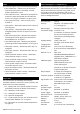
Relay Outputs
("8" in Figure 2.)
The two relay outputs provide voltage-free
changeover contacts, which can be programmed to
switch external equipment on or off.
Connect one side of the external device to the COM
terminal, and the other to either N/O or N/C. The
effect is as follows:
• If you connect to N/O, the contact between COM
and N/O is normally open, and is closed only when
the output is active.
• If you connect to N/C, the contact between COM
and N/C is normally closed, and is opened only
when the output is active.
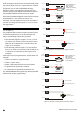
See Figure 13 for an example.
+12Vdc
0V
De vic e
COM
N/ C
N/O
Figure 13: Example of using a relay programmable output
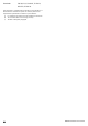
External Bell/Sounder Connections
("9" in Figure 2.)
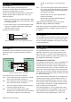
If required, an external sounder can be connected to
the control panel. Connection details are shown in
Figure 14.
Typical
Ex t e r n a l So u n d e r
Control Panel
H/O +
12V +
H/O -
0V
Tamper In
TR -
STB -
Tamper Out
TRG -
Strobe +ve
Strobe -ve
Trigger -ve
Figure 14: External Sounder Connections
The meaning of each terminal is as follows:
H/O+ This is used to provide a permanent +ve hold
off to external sounders, strobes, etc.
H/O - This is used to provide a permanent -ve hold
off to external sounders, strobes, etc.
TR - This is the negative tamper return connection
from the external sounder unit.
STB - This is the strobe trigger output, which
switches to 0V on alarm and is rated at 500mA.
Normally. this output is connected to the
strobe -ve; the strobe +ve is connected to
H/O+.
TRG - This is the bell trigger output, which switches to
0V on alarm and is rated at 500mA. This output
can be programmed for SAB or SCB operation,
and operates as follows:
SAB switches to 0V on alarm and provides a
maximum of 500mA.
SCB provides a negative hold off (500mA),
which is removed on alarm.
Additional external sounders can be driven from
MSNodes (using an RM3A relay module)
Note that the control unit provides a 14.4V supply for
recharging batteries in sounders used in France (“25”
in Figure 2).
Auxiliary Tamper Input
("10" in Figure 2.)
The AUX TMP terminals provide a tamper-switch input
for an auxiliary device such as a remote power supply
unit or extension loudspeaker. If the input is not used,
it must be linked out.
Line Fault Input
("11" in Figure 2.)
The system generates a line fault alert if +12Vdc is
applied to the LINE FLT input. If the system is unset
when this occurs, a "Chime" tone is generated every
minute until the condition is reset. If the system is set,
any programmed bell delay is cancelled.
Communicator Line Fault
If a standalone communicator, such as a RedCARE STU,
is being used, connect the Line Fault output of the
communicator to the LINE FLT input of the panel. The
communicator must provide +12Vdc to indicate a line
fault (e.g. if the Line Fault output at the communicator
uses a relay, connect the common terminal of the relay
to +12Vdc and the normally-open terminal to the LINE
FLT input of the panel).
If the communicator is dual-path (i.e. has landline and
mobile communication), you also need to connect a
panel output programmed as type "ATS Test" to the
ATS Test input of the communicator. Invert the sense
of the output at the panel if a "positive applied" input
sense is used at the communicator.
The panel generates an "ATE L.F. Single" alert if only
one of the networks is not available, or "ATE L.F. All" if
both networks are not available. For a single-path
communicator, a line fault generates "ATE L.F. All".