
Specifications


M2000 Installation Instructions 9
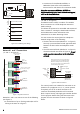
Figure 9. Fitting ADSL Filter ADSL01
Note: Make sure that you refit the jumpers to the pins shown in
Figure 9 if you remove the ADSL filter. If you leave the
jumpers off the telephone line will be disconnected.
The control panel has a Ringer Equivalence Number
(REN) of 0.2. For any one line, the sum of REN values
should not exceed 4.
Note: If you are in any doubt regarding connection to
the telephone network, seek advice from a competent
telephone engineer. If you are using the PSTN
terminal block, the wiring should be carried out by an
installer authorised by the network supplier (e.g.
British Telecom).
Approved Usage
This product is manufactured to meet all European
Economic Area telecommunication networks
requirements. The equipment has been tested and
conforms to ETSI TBR 21 and the associated ATAAB
Advisory Notes.
In the event of problems, first check to confirm the
functionality of the line, then contact your equipment
supplier/installer.
The built-in modem has been approved for the
following usage:
• Automatic call initialisation and dialling.
• Operation in absence of proceed indication.
• Modem.
• Serial connection.
• Multiple repeat attempts.
• Line Status Monitoring.
Usage other than approved usage or failure to comply
with the instructions may invalidate any approval given
to the apparatus, if, as a result, the apparatus ceases to
comply with the standards against which approval was
granted.
Digital Communicator Outputs
("6" in Figure 2.)
The control panel provides 16 programmable outputs,
which could be used to operate a digital
communicator – a device that transmits the status of
each channel to an Alarm Receiving Centre (where
each channel could represent a zone alarm status).
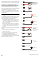
In addition to the screw terminals, the pcb also
provides two sets of pins for two plug-on wiring
harnesses (part number 485210). The bottom set of
pins provide communicator outputs 1 to 8 plus 0V and
12V. The top set of pins provide communicator
outputs 9 to 16 plus 0V and 12V. See Figure 10.
Figure 10.
Alternatively, low-power devices such as LEDs could be
switched on or off by these outputs (see Figure 11).
By default, each output is switched negative, i.e.
normally at +12Vdc and switches to 0V when active.
When at 0V, up to 100mA can flow into the output
from an external source.
If required, the sense can be reversed during system
configuration, i.e. normally at +0V and switches to
12Vdc when active. In this case, when switching to
+12Vdc, each output can deliver up to 5mA to an
external load.
The terminal block labelled "7" in Figure 2 can provide
a +12Vdc supply to a digital communicator. If this