CS 208 PROFESSIONAL AUDIO MIXER OPERATOR’S MANUAL 1411 Marsh Street, Suite 105 ! San Luis Obispo, CA 93401 ! (805) 782-9750 ! Fax: (805) 782-9752 www.coopersound.com 645 Main Street, Suite C Morro Bay , CA 93442-2273 Phone: (805) 772-1007 Fax: (805) 772-1098 http://www.coopersound.
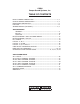
CS208 Cooper Sound Systems, Inc. TABLE OF CONTENTS INPUT CHANNEL DESCRIPTION ............................................................1, 2 OUTPUT MODULE DESCRIPTION ..........................................................3, 4 REAR PANEL DESCRIPTION ....................................................................... 5 PIN OUTS ..................................................................................................... 6 STEREO MODULE (OPTIONAL) .............................................
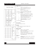
MODEL CS 208 INPUT MODULE Left Section 1. CH : Channel Power (down = on) Do not switch during recording. 2. PH / T : Phantom Power, ‘T’ power (AB). (phantom power is normally 48v, see layout A to change to 12v). 3. Mic Pwr : Turns on mic power (down = on). Mic power type selected by the switch above. 4. ø : N = normal, R = reverse. Audio phase only. 5. Mic / Line : Microphone or line level in. 6. Pad : Attenuator to reduce either mic or line input levels. 7.
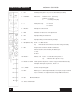
MODEL CS 208 INPUT MODULE Right Section 16. Gain : Mic / Line preAmp gain. 17. HF : High frequency amplitude control. 18. MF 500, 5k : Mid-frequency select. 19. MF : Mid-frequency amplitude control. 20. LF : Low frequency amplitude control. 21. S : Invert phase option to B & D busses. 1 pair of channels could be used to decode a M / S microphone configuration. 22. A1 : Aux 1 send (the aux sends are not affected by the AB, CD mix bus switches). 23.
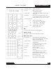
MODEL CS 208 OUTPUT MODULE Phones 2 & 3 1. PL : Private line assign to phones 2 or 3 (down = on). See master PL switch (27). 2. Main/Aux : Selects main (ABCD) or Aux 1 & 2 to phones 2 or 3. (Aux 1 = L out, Aux 2 = R out.) 3. AB / CD : When main is selected, this switch selects either AB or CD to L, R of the phone outs. 4. Rotary Select Switch : X = phones 2 or 3 follows the phones 1 selection. Example: Playback to phones 2 & 3 for director/ script critique. (Switch phones 1 to tape).
MODEL CS 208 OUTPUT MODULE 13. Comm. Trimmer : 14. T / D : Adjusts return level. Tape or direct to phones 1. See AB / CD below (16). 15. Main / Aux : Selects either main, ABCD or Aux (A1, A2) to phones 1. 16. AB / CD : When main is selected, group AB or CD is sub-selected to phones 1. This also controls the tape return (A = L, B = R, C = L, D = R). 17. Phones 1 selector : M = Mono to both outputs. L ST = A, C or A1 mono to both outputs. = A, C, A1 = L. B, D, A2 = R.
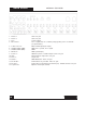
MODEL CS 208 REAR PANEL 1. Phones 2 : Stereo 1/4” jack. 2. Phones 3 : Stereo 1/4” jack. 3. Fuse : 4. Ext. Power In : 2.5A (5 x 20mm). Pin 1 = negative DC, Pin 3 = Battery charge (positive), Pin 4 = Positive DC 5. A, B, C, D, A1, A2 : Balanced XLR outputs (Pin 2 high) 6. Unbalanced Outs (TQG) : 7. Unbalanced Outs (DB9) : ABCD Pin 1 = ground, Pin 2 = signal. ABCD. 8. Mix Bus In : ABCD (current input). 9. Comm. In : 10. Slate : Talkback to phones 1. Balanced input. Stereo 1/4” jack.
MODEL CS 208 PIN OUTS All XLR’s are wired pin 2 high and are transformer balanced. XLR 3M Insert 1/4” stereo jack Tip = Send Ring = Return Sleeve = Ground or direct out, pre-fader (see app. note AN 2A & 2B) Pin 1 = Ground Pin 2 = High Pin 3 = Low Phones 1, 2, 3 1/4” stereo jack (max load = 25! per channel) Tip = Left Ring = Right Sleeve = Ground Direct Out (post-fader) 1/4” mono jack Tip = Signal Sleeve = Ground Mix Bus In DB9 Comm.
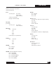
MODEL CS 208 CSST-STERE0 MODULE 1. CH. Channel power (down = on). Do not switch during recording. 2. PH/DYN/T Mic Power - Phantom = 48v * (see notes). Dynamic = no power. T 3. ø Audio phase only. = tonader power (AB). N = normal. R = reverse. 4. Mic/Line Microphone or line level in. 5. PAD Attenuator to reduce mic or line input levels. 6. HP1 High pass filter, pre-transformer. 7. HP2 High pass filter, post-transformer & pre-Amps. 8. Out (MS dec./LR) Down = no M/S decode. Up 9.
MODEL CS 208 CSST-STERE0 MODULE Specifications & Notes Reference = -8 PPM, 0VU Mic in (transformer balanced): Min. input level -83 dBu (Z in = 1.4 k!) Max. input, line position (no pad) +28 dBu Mic/Line pad PAD Combined -40 dB Zin " 10k! -15 dB Zin " 600! -55 dB Zin " 10k! High Pass Filters: HP1 100 Hz at 6 dB / oct HP2 O/L indicator 70 Hz at 12 dB / oct 3 dB below M. O. L. (max output level) Response 20 - 20 kHz +/- 0.5 dB EIN (20 - 20 kHz, 150!) THD + N (20 - 20 kHz) - 129.5 dBu .
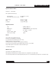
MODEL CS 208 SPECIFICATIONS General: (0 dBu ! .775v RMS) Dimensions 16.5” x 15” x 5” (419 x 381 x 127 mm) Weight with no batteries with alkaline cells 19 lbs. (8.6 kg) 23lbs. (10.4 kg) Overall distortion (THD + N) < 0.01% (0.003% typ.) Equivalent input noise (150" 20-20kHz) (150" ‘A’ WT’D) -129.5 dBu -131.2 dBu Power Requirements: External: 10v - 25v operating range. Consumption with all channels on is ! 630 mA at 12v DC < 8 watts (410 mA at 18v DC).
MODEL CS 208 SPECIFICATIONS System Power Connections and Precautions: RE: (+) chassis equipment. The Nagra 4.2, IVS must have a separate supply, with no common power supply connections to the mixer or other (-) chassis equipment. Input: Reference: -8PPM, 0VU (XLR’s are pin 2 high). Mic In: (Transformer balanced) Minimum input level Maximum input, line position (no pad) -83 dBu (Z in 1.
MODEL CS 208 SPECIFICATIONS Output: Reference -8 PPM, 0VU (XLR’s are pin 2 high) XLR balanced outputs: A, B, C, D & Aux. 1, 2 +4 dBu, Zout ! 100" TQG & DB 9 unbalanced outputs: (ABCD) Phones 1 out: -2 dBu, Zout ! 100" 0 dBu no load 0 dBu 60" load Phones 2 &3: -3 dBu no load -8 dBu 60" load Maximum load is 25" for each output: Tape return (balanced) -14 dBu to + 19 dBu Zin = 10k" Communication in (balanced) -14 dBu to + 19 dBu Zin = 10k" Ext.
MODEL CS 208 BLOCK DIAGRAM 12
BLOCK DIAGRAM 13 MODEL CS 208
MODEL CS 208 EQ CHARTS 2 1 3 1=HP 1 2=HP 2 3=HP 1 + HP 2 14
LAYOUTS 15 MODEL CS 208
MODEL CS 208 LAYOUTS 16
LAYOUTS 17 MODEL CS 208
MODEL CS 208 CSST - LAYOUTS 18
BASIC SET-UP & METERING MODEL CS 208 OPERATING GUIDLINES Levels CS208 PPM Adjust Input for 0VU Analog recorder with peak meters eg: Nagra -8dB modulometer Ref. Level -8PPM (Master pot at max) CS208 VU Analog recorder with VU meters Ref. Level 0VU (Master pot at max) DAT, Digital Camera -18, -20dB* * refer to manufacturer’s specifications 1. Set master faders (including Aux) at maximum. * 2. Adjust internal oscillator for -8PPM (0VU) on the mixer meters (If necessary). 3.
MODEL CS 208 BASIC SET-UP Recorder Connections: There are 2 types of outputs provided - balanced & unbalanced. In general, the unbalanced outs are used to connect to unbalanced inputs. eg: Nagra 4.2, IVS, wireless transmitters, semi Pro DATS. The balanced outs are used for balanced inputs, long cable runs, & feeds to unfamiliar equipment. eg: Video Assist, guest crews, etc. (The transformer balanced outputs will provide greater isolation & protection from these devices.
OPERATIONAL & APPLICATION NOTES MODEL CS 208 Inputs: XLR In: Transformer balanced input. Nominally Pin 2 high. (Pin 3 - low, Pin 1 - ground). Channel Power: To conserve current consumption, switch off unused channels. Do not switch during recording. Mic Power Select: ` Mic power off. For example, dynamic and radio microphones. T-power/AB power = Unbalanced microphone powering, nominally Pin 2 is positive, for use with unmodified European microphones. XLR must be reversed for ‘red dot’ microphones.
MODEL CS 208 CD in: OPERATION & APPLICATION NOTES Assigns channel to CD mix busses via the pan pot. A,C = Left B,D = Right (eg: To assign channel to A only - AB in, CD out, pan left). Limiter: Attack and release times are preset internally. There are jumpers to change the attack and release times. (See application notes AN 2D.) Attack: Too fast an attack time will attenuate the leading edge of the wave form, therefore changing the sound characteristic.
OPERATION & APPLICATION NOTES MODEL CS 208 Insert: Post HP filters, EQ. & Limiter. Send and return to auxiliary equipment (eg: outboard compressor/limiter, equalizers and multi-track recorders). Can be changed to direct out, pre-fader only. (See application note AN 2A & 2B.) Direct Out: Post channel fader (eg: feed to playback systems, direct feed to multi-track recorders). 2 Holes above Ch. 1 & 2 on rear panel: Machined for XLR connectors (eg: stereo input channels).
MODEL CS 208 OPERATION & APPLICATION NOTES T/D (tape, direct): Tape return is also selected by the AB/CD switch. Comm. in: Comm. return level controlled by trimmer below. ‘PL’: Assigns PL to phones 1 (Down = on). Phones select: M.S.: Phones pots 1, 2, 3: M = Mono. L = Mono to left and right capsules (either A, C or A1). R = Mono to left and right capsules (either B, D, or A2). Mid, side decoded to L, R stereo, phones only. To adjust level to phones 1, 2, 3 (stereo output).
OPERATION & APPLICATION NOTES MODEL CS 208 ‘Phones 2 & 3’ ‘PL’ assigns private line to these outputs. Main to AB/CD Assigns either A, B or C, D to the phones outputs. Main/AUX Assigns either main A, B, C, D or Aux. 1, 2 to the outputs. (Note: Left out = A, C, A1; Right out = B, D, A2.) Phones Select Further sub-selects signal to the outputs. (eg: Phones 2 could be A only.) (Main to AB to L.) X Phones 2, 3 follow the phones 1 selection.
MODEL CS 208 AN1 REMOTE ROLLS TQG TB 5 M BD. G INTERNAL NAGRA 2 1 6 2 STOP -10 2 6 STOP 1 2 -10 DIODES ONLY NECESSARY IF TWO NAGRAS ARE CONNECTED.
AN 2A - INPUT CHANNEL OPTIONS MODEL CS 208 Direct Outs & Inserts Standard configuration is Insert point (send/return) & Direct out post-fader. For flexibility in the field, J5 is normally set at the B2 position, so the Insert jack can be either Insert or Direct out pre-fader, depending on how the connecting cable is wired. ie: For Direct out, pre-fader - jumper tip & ring of a 1/4” stereo jack plug. To change Insert to Direct out, pre-fader only, move shunt to position A2 (J5 board A).
MODEL CS 208 AN 2B - INPUT CHANNEL OPTIONS Direct Out, Pre-Fader Level Boost The nominal level of the Insert jack send/Direct out, pre-fader, is -5dBu. If the Insert jack function has been changed to Direct out, pre-fader, (see AN 2A), the level can be increased 9dB for a nominal level of +4dBu. (see note 1) The following components will need to be installed on board A. (These components are not normally installed to conserve current consumption.
AN 2C - INPUT CHANNEL OPTIONS AFL, PFL MODEL CS 208 (J6) Normally set for PFL (pre-fader listen) (position B). PFL level to the phones is approximately equal to the level through the mix busses with the input fader at 0, & the pan pots panned either left or right. If changed to AFL (after fade listen), the level will be approximately 3 dB higher with the fader at ‘0’. LED = O/L or Limiter J7 A = limiter. B = O/L only (standard configuration).
MODEL CS 208 AN 2D - INPUT CHANNEL OPTIONS Limiter Threshold Threshold - normally set at +4 PPM, with the input fader a ‘0’. Attack & release times are normally both set for ‘fast’. J3(A). Should the attack and/or release times settings be changed, the threshold may need to be readjusted. Limiter Threshold Adjustment (no external test equipment required.) * Assign oscillator to C,D only (or Aux only). * Switch input channel to Line in.
AN 2E - INPUT CHANNEL OPTIONS MODEL CS 208 M/S Decode Option See layout B. Standard setting: J4 is jumpered & J3, J5 are open, U2, S3 etc. are not installed. One or more channels may be set up to decode an M/S mic configuration. For example: To set up channel 2 - Install components on board B as below: S3 BB26AH U2 TL071 / OP176 C13,15 47µ - 25v (electro) (SU) C14 X3, X4 10PF NPO ceramic .1µ ceramic (general purpose) R20 120k 1% MF 1/4w R21,22 R23 100k 1% MF 1/4w 47k 5% / 1% 1/8w J3 Jumper .
MODEL CS 208 AN 3 - COMMUNICATIONS IN - MULTIPLE INPUTS The communications input can be used with multiple inputs (eg: 2 boom operators) by using a special adapter cable (see below). The communication in connector on the rear panel is balanced. Tip = Hi, Ring = Low, Sleeve = ground. For multiple inputs, the ring should be grounded. This is done either by use of a mono jack plug for the adapter cable, or using a stereo jack plug & shorting the ring to sleeve.
GENERAL NOTES MODEL CS 208 Standard Configuration All audio connectors are pin #2 hot. Mic ‘T’ powering is: Pin #2 + 12vDc. Alternate phase to be specified at time of purchase. Levels are set as specifications. Meter types should be specified at time of purchase. Access to Output Trimmers All trimmers on the output module are accessible by removing the right side panel only (no need to remove the module). Tools: 1/16” & 5/64” Allen wrenches.
MODEL CS 208 LIMITED WARRANTY 1. Warranty registration must be completed and mailed to Cooper Sound Systems, Inc. within 30 days of the date of purchase. 2. Cooper Sound Systems, Inc. warrants the materials and workmanship of this product for a period of one year from the original date of purchase. If any defects are found in the materials or workmanship within the specified warranty period, Cooper Sound Systems, Inc. will repair or replace the product, at its option. Please note the following: A.